
.png.5a0f08430bae173944a56977dd41765f.png)

Muhammed Sarikaya
-
Posts
58 -
Joined
-
Last visited
Posts posted by Muhammed Sarikaya
-
-
Dear Claire,
It seems your view is in 'perspective view'; maybe you should try clicking on the 'Orthogonal Projection' button, and you will see your table at the same height.

Regards,
Muhammed Sarikaya
-
Dear Nikoloz,
Thank you very much for your suggestion. I will inform our development team about this feature.
Regards,
Muhammed Sarikaya
-
Dear Sarah,
In the previous project description, it seems that the PV array consists of fixed-tilt PV tables initially oriented towards the east and west. Due to the topography, the orientation of all tables will change, which is why it results in eight orientations.
What you mentioned about the horizontal N-S axis is used for tracking systems.
Tracking, horizontal N-S axis: this is the usual configuration of horizontal axis tracking systems.
Is this clear enough for you? Please don't hesitate to write to us."
Regards,
Muhammed Sarikaya
-
Dear Sarah,
I invite you to watch this video to understand how you can import a 3D scene into PVsyst.
I don't understand your second question. Could you elaborate and explain what you need clarification on?
Regards,
Muhammed Sarikaya
-
Dear Edwin,
I can suggest you to read this post:
The LID effect only arises with conventional p-type boron-doped wafers. Unconventional technologies using n-type doped wafers (as for example SunPower mono-facial cells) are not affected.
LID is a loss of performances arising in the very first hours of exposition to the sun, with Crystalline modules. It may namely affect the real performance with respect to the final factory flash tests data delivered by some PV module providers.
This loss is permanent over the entire lifespan of the PV module.
Regards,
Muhammed Sarikaya
-
Dear Irakli,
When running in DEMO mode (after the license has expired), you can operate the program and explore all options.
You can open existing project files (especially the DEMO projects), view parameter definitions and results, but you cannot save any files.
You will only have access to a restricted set of components in the database.
If you created a project during the trial license period, you can save your project and continue using it after you purchase the license.
Regards,
Muhammed Sarikaya
-
Dear Shivam Pandey,
It depends on you. How did you import or create the horizon line?
If you imported it from Meteonorm or PVGIS, the horizon is reliable, and you can use it for your simulation.
Regards,
Muhammed Sarikaya
-
Dear Irakli,
PVsyst is not responsible for the actions of its users, and we do not verify whether the results are accurate. We can only investigate in the event of a bug to determine its cause.
Additionally, I should mention that the azimuth in your projects appears to be incorrect. Please be aware that an azimuth of 0 in PVsyst corresponds to the direction of the sun.
Regards,
Muhammed Sarikaya
-
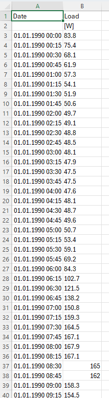
Dear MEURVILLE,
You must folow this model :
You must use the names 'Date,' 'Load,' and '[W]' at the top of the cells so that PVsyst can accept this load profile.
Regards,
Muhammed Sarikaya
-
Dear Giulio,
Unfortenately, we can't see results for every single inverter or subarray.
Regards,
Muhammed Sarikaya
-
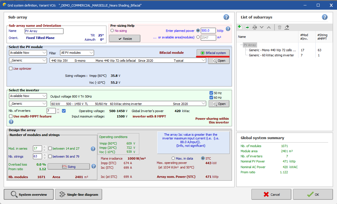
Dear Vera,
In your print screen, the bifacial module is not active as the green LED is not illuminated.
Here is an example of the bifacial module in use:
Regards,
-
Dear Rohit Rana,
Could you please send your project to our support email: support@pvsyst.com?
We need to investigate why you are experiencing this issue.
Regars,
-
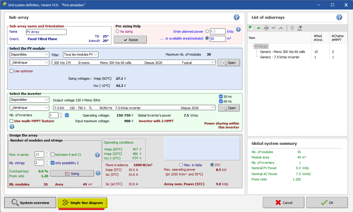
Dear Estagiario,
In the 'System' window, there is a button labeled 'Single-Line Diagram' below. You can click on it to visualize.
Regards,
Muhammed Sarikaya
-
Dear Muhammad,
I think you haven't activated 'power sharing' because the buttons in the single-line diagram are not active. Could you please share a complete screenshot of your windows? That way, I can understand better why you're experiencing this problem.
Regards,
-
Dear Muhammad Faizen,
The reason the SLB (Single Line Diagram) button is inactive is due to the illogical distribution of your modules across the MPPT (Maximum Power Point Tracking) inputs. You are attempting to distribute 7 strings across 5 MPPT inputs. While you can proceed with the simulation, you won't be able to open the "Single Line Diagram".
Regards,
Muhammed Sarikaya
-
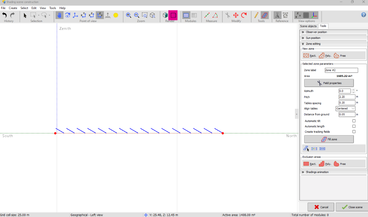
Dear Mohamed,
You can conduct your project with the panels mounted on a fixed tilt plane. To enable bifacial calculations for a fixed structure system, activate the bifacial model and then select 'Use Unlimited Sheds 2D-Model'.
Regards,
Muhammed Sarikaya
-
Hello,
You can only choose from the available cable sections. I suggest selecting the highest section to simulate pessimistic results.
Regards,
-
Dear Somasekhar,
Please read this help page of PVsyst:
https://www.pvsyst.com/help/index.html?thermal_loss.htm
You will understand the reasons behind the ability to decrease or increase the thermal loss factor.
Furthermore, in our YouTube video tutorial, within the "Thermal Behavior" chapter, we explain how you can adjust this parameter.
Regards,
Muhammed Sarikaya
-
Dear Mohsin,
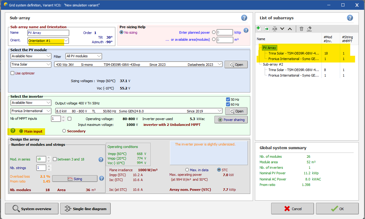
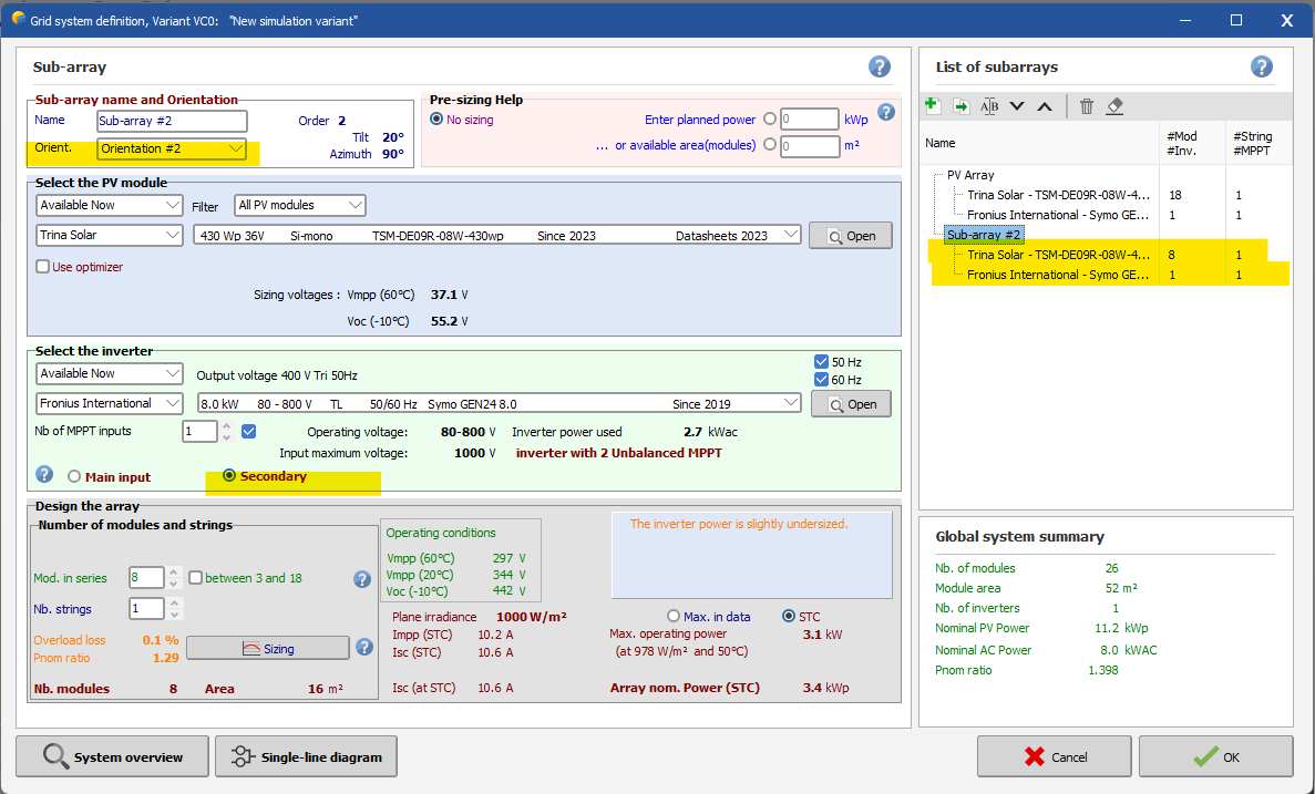
First of all, in PVsyst, azimuth 0° always represents the direction of the sun. In your case, when you input 180°, it means your PV modules are facing north. You mentioned having a roof with two different tilt angles, but you didn't specify the azimuth angles. Usually, when installing PV modules on a tilted roof with multiple orientations, you need to define both the tilt and azimuth angles of your roof.
Additionally, in the system setup, you need to create two subarrays for each orientation. Here is an example with a screenshot:
Please be cautious because the inverter you have selected have unbalanced MPPT (Maximum Power Point Tracking). You should configure the Main Input with a higher PV array capacity than the second input. You can check this in the two screenshots provided.
If you have any question, don't esitate to write me.Regards,
Muhammed
-
Dear Georgy,
I can't answer you because it depends on multiple variables.
In PVsyst, you can't set different orientations within a series of modules.
I suggest increasing the detailed losses for mismatch in your simulation. The idea is to simulate the worst-case scenario. That way, when you install your PV modules, the actual electrical production will likely be higher than the simulation.
Regards,
Muhammed Sarikaya
-
Dear Vera,
Today you can do this project separately by creating two distinct project.
Regards,
Muhammed Sarikaya
-
Dear Michalis Angeli,
You can mix only 2 orientations.
Regards,
Muhammed Sarikaya
-
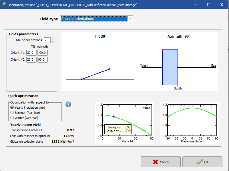
Dear Marcoz15
It's very simple; first, you need to select "Orientation" and choose the field type as "Several orientations," as shown in this image:
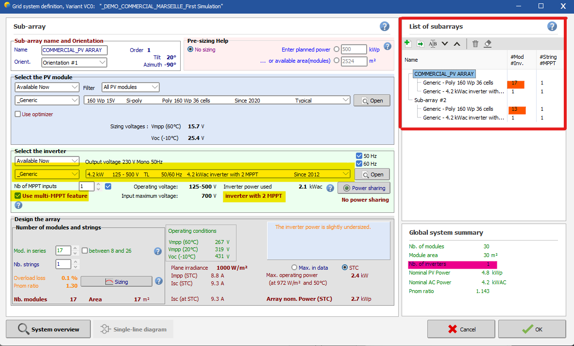
Then, when configuring the system, there are a few things you need to be careful about:
In the "List of subarrays," you should create two subarrays. When selecting your inverter, make sure it has a minimum of 2 MPPTs. Activate the multi-MPPT feature, and don't forget to assign the orientation for each subarray.
Does that make it clearer?
Regards,
Muhammed Sarikaya
-
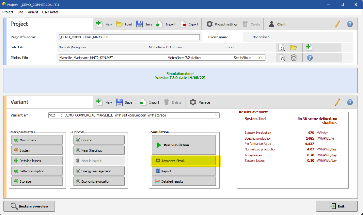
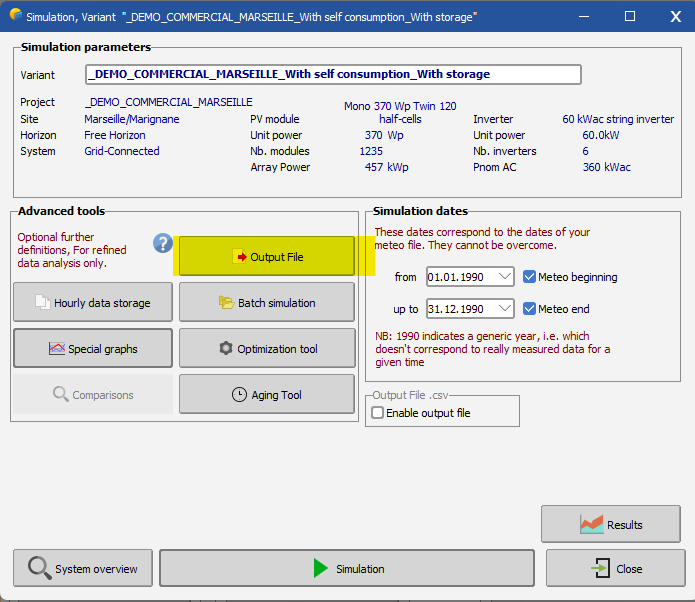
Dear Mohamed,
You can export your result with advanced simul.
Click on advance simul.
Click on Output File:
Next, you need to select the name for your output file and confirm the simulation variables you want.
In this same windows, you have to click on "Simulation" if you want to generate a csv file that can be opened in excel.Regards,
Muhammed Sarikaya
Different azimuth in Near Shadings and Orientation tabs
in How-to
Posted
Dear Irakli,
It's possible to change these values. If you select all the tables, your modification will apply to all the selected tables.
To modify the tilt, for example, just click in the box where you want to change the value, and it will be applied.
Regards,
Muhammed Sarikaya