


Fredy
-
Posts
30 -
Joined
-
Last visited
Posts posted by Fredy
-
-
Good Morning
I’m using the New Version of PVsyst 6.68 and when I do "Construction / Perspective" I usually import from Helios3D
i have an Pitch on the Layout but in report it always show 5m (I’ve tested in different layouts with different distances its always 5m on report)
Is there any way to remove this option from the report like in the previews versions?

-
Good afternoon
Im revewing an old simulation and with the exact same IAM profile i get diferent losses in the end
(this profile is imported from .PAN file, in the V6.67 i had to copy the values)
is there any explanation for this or is it an error??
IAM profile
6.65
6.67
thank you for your support
Best reggards
-
Hello
We are trying to do montlhy PR calculations, but when we do the final monthly average the value is different from the PVsyst final PR
Could you please help us with this issue?
Thank you for your support
Best Reggards
-
Hello
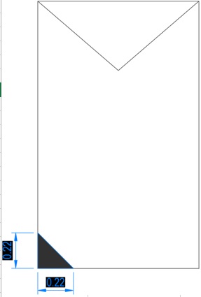
In module Layout I’m trying to simulate the dirt and dust loss that accumulates in the corner of the modules:
Is it Possible to do this in the module layout? Add a triangle as an “Inactive area of the modules?
I can’t see the Option to add a shading area is it bugged?
I’m using PVsyst 6.39
Thank you for your support
-
Hello
I need to set smaller time intervals to measure the angle of a tracker
In this simulation our tracker is a tilted axis tracker with:
Axis tilt: 0
Axis Azimuth: 0
Phi min.: -45
Phi min.: +45
I see in near Shading the "Shadow animation" gives us sun azimuth and sun height each 15min
Can we Export a table with the following data:
Time: 00:00 ; 00:15 ; 00:30 etc... 23:45
Sun azimuth
Sun height
Phi angle (-45 : +45)
Thank you for your support
-
Good afternoon
I'm comparing 3 different Meteo databases and in this 3 simulations i used all parameters losses modules inverters are the same just changed the Meteo,
I get the following results:
I don’t understand why Meteonorm VS PVgis have almost the same Global Radiation and the PR changes so much (81.6 - 82.2)?
and Meteonorm VS Meteosat have the same difference on PR (81.6 - 82.2), with lower radiation and higher GlobINC i have more gain in (Hor / Inc) that i understand
Is there some other parameter that affects this when using different Meteo files?
Thank you for your support
-
Hello
I have the PVsyst 6.39 Version andI'm having trouble importing an inverter File from Version 6.43:
I get this error:
Is there any way to import recent files to old versions of PVsyst?
thank you for your support
Best reggards
-
Hello
I had to come back at this Post because,
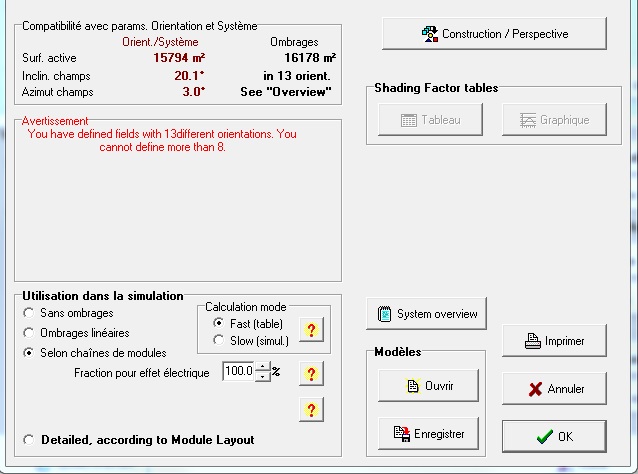
We are trying to find out how the azimute was calculated when we have multiple orientations and we had to use higher "Discriminating orient. difference between shading planes", we did several tests
the azimuth it show's on the image bellow:
Is the azimut of the "Main Table" the one that we creat first or in cause of Helios 3D it alwas show the same azimuth in "constraction prespective" im assuming it is average? or is it the azimute of the "main table"?
We are now doing a project with very hight slopes
what's the best since PVsyst "during the simulation, the incident irradiance will be calculated once for the average orientation, and applied to all tables in the same way, resulting in a (little) orientation loss."
We wanted to know how should we treat this case?
Should we add some losses to consider this "orientation loss."?
-
Same problem here
I'm missing the Iso-shadings diagram on some PDF-Printouts sinsce 6.37.Iso Shading diagram doesn't show on the pdf reports
-
Hello
I'm trying to do a few simulations with the Design on Helios3D with multiple tilts (Multiple helios3D files) then i combine the CSV files in order to see the production / PRs for the PV plant with the tilts corresponding to the days i find better.
When using daily values we get some PR's that doesn’t make sense and when i do the average PR I get lower PR with this multiple tilts but better production
On the CSV with the multiple tilts I’m excluding Values under 10% of the maximum value for each month and it gives me something near the average PR of the 3 Tilts configuration
But I don’t know if it makes sense either the PR should be +/- constant because if we have low irradiation the production should fall down as well making the PR +/- the same as a high Irradiation day?
At least when we measure with our pyrometers the PR goes +/- constant with low deviations between max and min and without that low values that shows on the image bellow
Do you have any idea how to make this seem right?
This image is just an example of the PRs from 1 month
Thank you for your support
-
Hello
Is it possible to import trackers from helios3d?
Or to import an fixed layout and convert the tables into trackers?
Look forward for your feedback
Best regards.
-
Hello
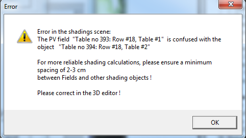
I'm doing some big PV plants and i got this error in one of them:
When we have big slopes on helis3D sometimes this happens.
Is there any way to simulate even if this happens, anything on the hidden parametters or something?
Best reggards
*PVsyst 6.34
-
Thank you for your help,
Ok so PVsyst considers some days covered cloudy?
Normally I see monthly values when importing from external Meteo data
This hourly tables are interpolated by PVsyst when we do the synthetic hourly data generation?
It is a probability calculation?
Sometimes 0 for beam irradiance and sometimes x% for Beam irradiance?
Where can I find this?
Thank you for your support in advance
-
Hello I’m sorry for the spam
I found that for Horizontal Beam there are some values missing or low values a lot actually,
Maybe this could be the reason why I’m getting this
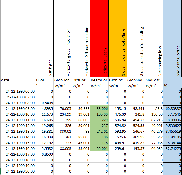
For this test I’m using another Meteo file from PVGIS On the first Post I was getting BeamHor = 0 in every cell for 21-December, but now even with this one from PVGIS there are some missing values.
In the images bellow the red/green cells corresponds to the acceptable / unacceptable values for BeamHor
Blue Cells were calculated: (ShdLoss / GlobInc.) to have a perception of the loss %
In this table we can see that there are some missing values and low values that doesn't make sense more losses at the mid of the day then at morning
I found this one acceptable at least make more sense than the other two
This one seems good too more losses at morning/afternoon and less on mid-day
It was harder to find correct values then wrong / missing values.
1- Could you see if this is a bug from the program it fails to generate some values or something?
2- The program calculates the shadows for every hour with the corresponding shading factor but it needs the beam Irradiation right?
Thank you in advance for your support
-
I was analysing the output file tables and for what i understand PVsyst is taking the shading loss constant for all the hours
So PVsyst just uses the Near shading Table and shading factors to calculate 1 final Shading loss that is used constant in every hour?
Shouldn't it use the shading factores that it calculates in the near shading table to get the values for GlobEff / EARRay etc... correctly for every hour?
-
Hello
We are having a problem with the production in a plant that is already working, we are having half the production that PVsyst gave us
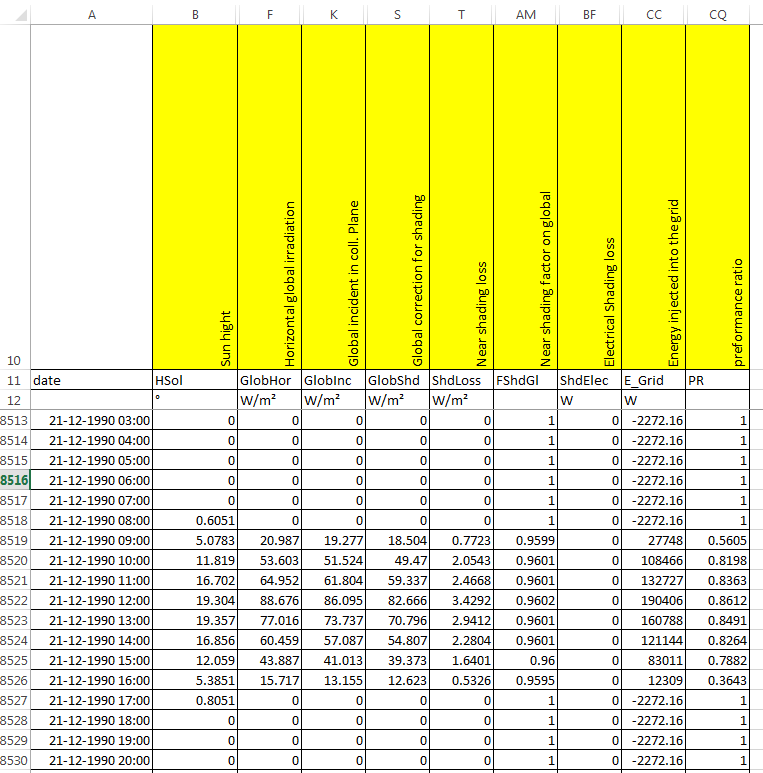
I found this values referent to shadings in the output file:
the Near shading Animation corresponding to this table is the image bellow (it’s just an part of the plant + shading factors and graph):
So could you clarify the meaning of this values on the output file?
-Global correction for shading: Irradiation reaching the modules counting with the shadings?? If it is correct shouldn't it be lower for example at 9:00h globInc=19.277 GlobShd=18.504 it is just 0.77w/m2 difference and on the near shading animation I see almost all the plant shaded at 21-12 _ 9:15h
-Near Shading loss (w/m2): I don’t understand this one. Is it the quantity of irradiance loss due to shading? Why I have more losses at 12:00h than at 9:00h?
-Near shading factor on global: Globshd / GlobInc OK. This should be the % of irradiance loss due to shading but because of the previews parameters we are having more losses at 12:00 than at 9:00...
Is PVsyst taking this shading losses correctly it seems
Is there any other parameter i can use to see the shading loss % ?
Thanks in advance for your help
-
Hello
In a PV simulation should we consider using the Light Soaking effect of the CIS modules?
It increases the PR a lot and I don’t know if this effect takes place for a long period of time or just for 1 year or a shorter time?
The module im using is Solibro 125Wp witch has +2.5% Light Soaking effect
With this increase of performance this modules takes advantage by all the other modules,
I'm a bit afraid of giving this hight values to our clients (86%PR in France lat:44.4°N), should I simulate with or without light soaking effect?
Thank you for your support.
-
Dear André
I'm using all that options:
Near Shading Calculation mode -> Fast (table)
Not using "Module Layout"
On 3d editor i have that option checked "Tools" / "Optimized calculation"
My system is about 896 objects tables (on 3d model), and 8 central inverters.
it takes almost the same time as the Near shading table.
This is stressfull when you have to do several simulations where you change one loss or one other parameter you have to wait all that time again.
do you know what can be causing this?
Best regards
-
Any news regarding this problem?
I've updated to 6.30 and on this part like "Denizurla" referred:
The simulation it’s too slow it takes like the same time as the Near shading table calculation, or more..
Is it normal to take all that time?
Previously it was like “instant” in PVsyst5 let’s say 1 minute in the worst cases.
Why does it takes hours now?
-
yes i forgot to mention that i use 100% fraction for electrical effect.
and as you told me:
If you use 100% for this factor, then your comment is right, it would not be necessary to calculate the linear shadings, since you loose all the string production.so this would be an additional loss that is already included in "Shading: Electrical loss acc. to strings"
Is there any away to remove the linear for simulations with 100% electrical effect?
because if we have 2 shading losses its like we have 2 shades on the top of each other.
-
Hello
I’m sorry for the question:
But is it normal to have both losses on the simulations?
-Near Shading Irradiance loss (= Linear shading) +
-Shading: Electrical loss acc. to strings
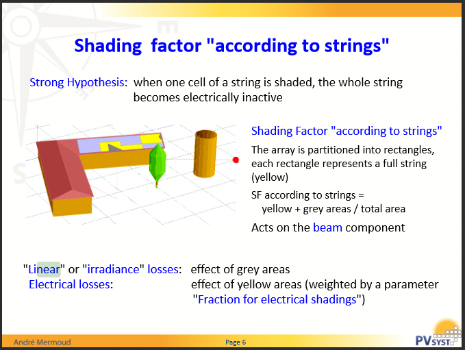
Shouldn't we have just 1 loss "Shading: Electrical loss acc. to strings", as it englobes the linear + the string that belongs to the shaded module?
Is it normal to have less production/PR with simulation according to module strings?
Of course the yellow area on the image above is bigger than the gray area.
- What I don’t understand is the linear shading is like a proportion of the shading area VS active area.
This should be like just the geometrical part of the shading?
- And the electrical effect should be when 1 module is shaded the whole string is inactive. But shouldn't that electrical effect be the only shading loss on the report?
It’s like we are adding 1 loss instead of changing the calculation method to the “according to the module string”.
It calculates geometrical + electrical?
Tell me if im wrong! Maybe I’m misunderstanding something?
How is this calculated?
Thanks in advance
Best regards
-
Hello
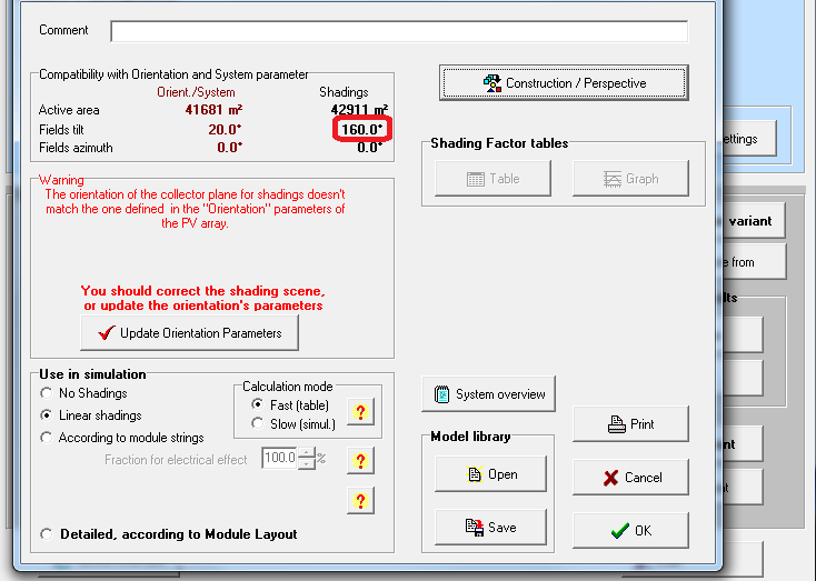
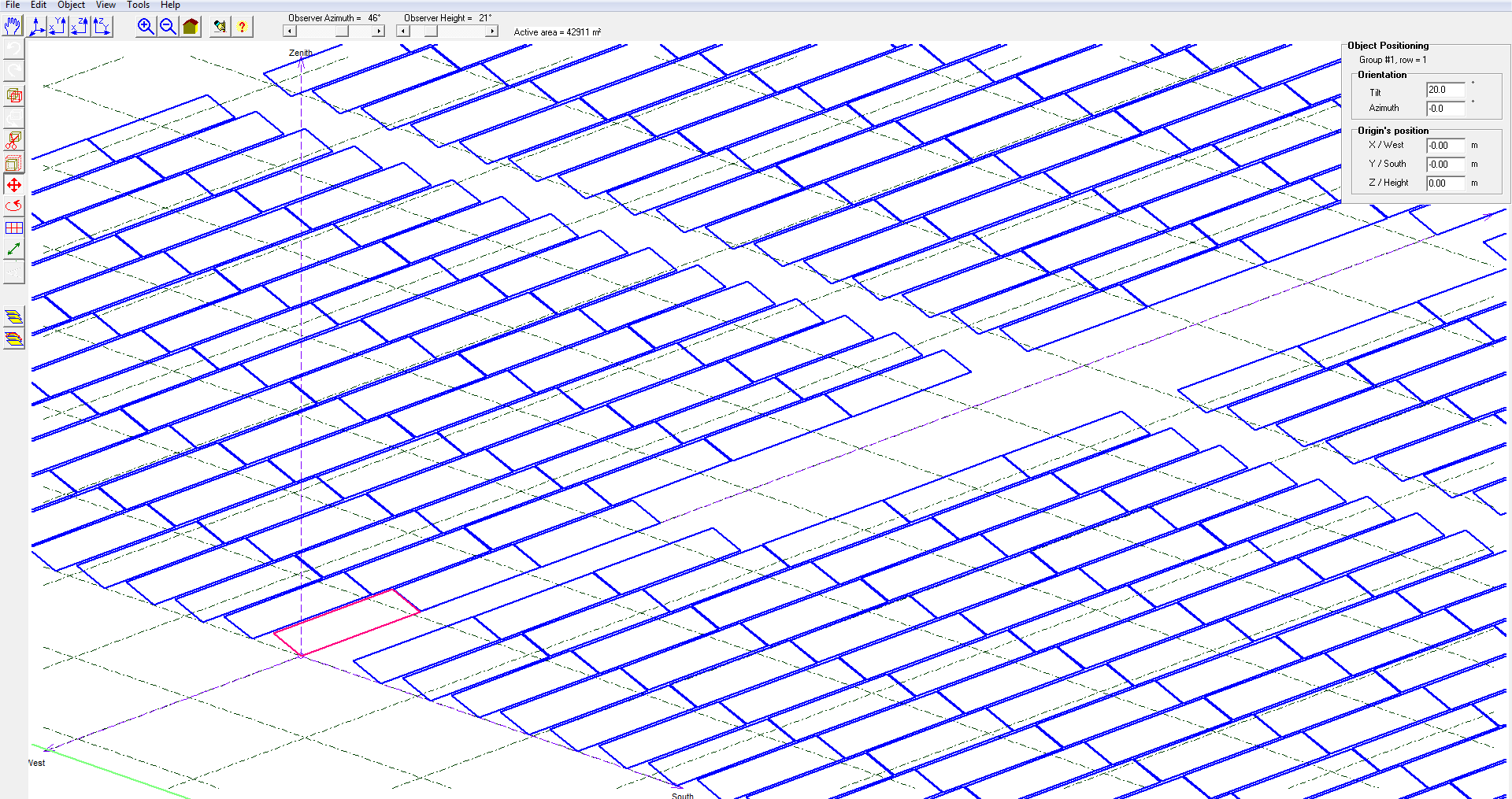
I have to make an simulation with PVsyst 6 near Dubai latitude 24°
and when i import the plant from Helios to the near shading Construction / Prespective the tables are facing North when they should be facing south
and it asks me for an tilt angle of 160º
If i use the same file on PVsyst 5 it gives me the correct tilt angle 20º south
I checked everything on helios is correct and it is ok in PVsyst 5
Is anything i have to take in to account in PVsyst 6?
Can this be fixed?
Thank you for your support
-
Hello
In PVsyst 5 we could control the "Shading max. orientation difference between shading plans" on the hidden parameters so you could simulate even if the difference was too big (bad terrain)
Now in PVsyst 6 I can’t find an parameter where I can define the nº of orientations (see image attached)
Is there any parameter to define this limitation?
So PVsyst could make an “average” of the orientations?
Thank you for your support.
-
Hello
I've just updated my PVsyst from 5 to 6
I have exactly the same problem
i work with large scale palnts and on that screen "Hourly simulation Progress" it is very slow
Is there any option to simulate faster?
Or is it a problem from the program?
Look forward for your feedback.


PVsyst 6.68 Pitch Repport
in Problems / Bugs
Posted
Good afternoon
I’ve updated PVsyst to v6.70 but this error is still there.
I've noticed why PVsysts always assumes Pitch (Sheds spacing in 6.7) 5m in the report when you import a layout from Helios3d.
When you go to construction perspective and open a single table that you imported from helios3d the default values for pitch is 5m.
But this is wrong in the full layout we have different pitch so is there any way to remove this option from the report or fix it?
Thank you for your support