Abdel
-
Posts
26 -
Joined
-
Last visited
Everything posted by Abdel
-
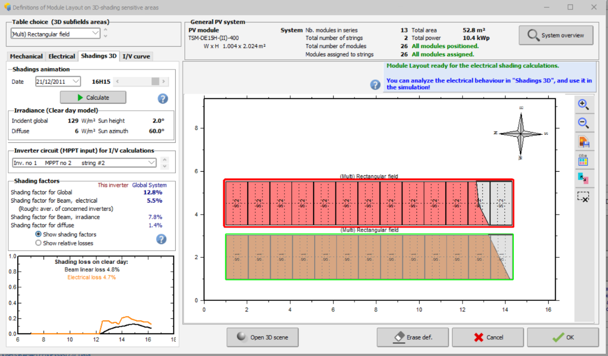
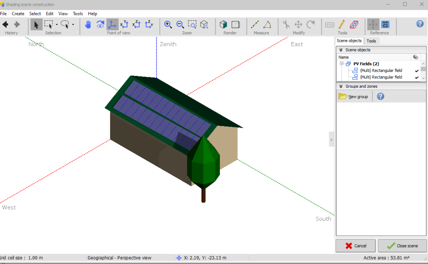
The two strings are clearly on separate MPPT inputs, and both strings are not partially shaded. the shading is made just for PV string 1 and the another string 2 is free of shading but the system still gives electrical loss for it !!! The time is the same for 3D editor and Module layout which is 21/12/2011. It is very strange that why PVsyst considers the system as one MPPT . Please can you give explanation about that ?

-
Hi, It seems that PVsyst has wrong assumption but I hope to finds an answer from PVsyst team for my question I have system of 10.4 KWp and inverter of 10KW. The system consists of 2 PV strings and the inverter has 2 MPPTs , which means each PV strings will be connected to one MPPT. I have made shadow on one PV string caused by tree and another PV string is free of shading. Now in Module layout when I want to see the shading losses for each string, it seems PVsyst consider the system as one MPPT because PVsyst gives me 5% of electrical loss for unshaded PV string and this clearly wrong for the calculation and final results. Now my question, Why PVsyst gives me 5% as electrical loss for unshaded PV string? is it wrong assumption ?
-
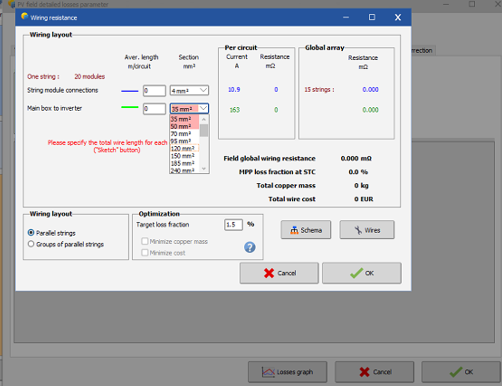
Hi folks I hope to find the interest in my question I am wondering if there is an error in PVsyst regarding the calculation of ohmic losses !! I have a system of 111 KWp with an inverter of 100 KW Huawei. The system consists of 15 PV strings connected to MPPTs Huawei Inverter. The Inverter has 10 MPPTs, each MPPT has 2 inputs, which means that the strings will be attributed on MPPTs of the inverter and there is no parallel-connected strings. Now my direct question is related to the Ohmic losses . In PVsyst there are just two options in the wiring layout: 1- Parallel strings 2- Groups of parallel strings I am wondering How can I choose that every string is connected directly to the inverter (in my case I don't need a combiner box) without having a combiner box? How can I choose a case that I have just PV strings are connected directly to MPPTs inverter without having combiner box, because the cable size would be 6 mm2 but PVsyst doesn't give me that option?
-
Thanks brother
-
Hi folks Regarding to ohmic losses. I have system consists of 120Kwp (PV modules) and 100KW inverter power. The system consists of 18 PV strings , 18 PV modules per string. I want to connect directly 18 strings on 10 MPPTs/20 Inputs , which means that I don't need combiner box in the system. Now for ohmic losses , PVsyst define combiner box for the calculations and there is no option to skip it . My question , how I can calculate the power loss if I have for example 18 PV strings connected directly to the Inverter MPPTs inputs without combiner box in PVsyst ? ?
-
Hi, IS there any solution for this problem ?
-
Hi, I have simple question which confused me a lot What is the difference between Fixed tilted plane and unlimited sheds in PVsyst ? in PVsyst help document, it mentioned for unlimited sheds that "the sheds are very long with respect to their width", so what does it mean also in this case by this sentence?
-
Thank you
-
Thank you so much
-
Hi, I understood that I must choose one out of these two options "planned power and available area" , but my problem is that, if I have choose as an example "available area" which refers to the PV modules area (without considering the tilt angle and the distances between the PV modules rows) , then in this case How I can estimate this option based on my building area? in simple words for example in Helioscope software (just an example to explain my case) , you define specific buidling area then the software set directly the PV modules based on available building area ,defined tilt angle and rows distances . Now if we compare this to PVsyst , how I can do the same logic ?
-
Hi Basson, Thank you for your explanation! I understood that I must choose one out of these two options "planned power and available area" , but my problem is that, if I have choose as an example "available area" which refers to the PV modules area (without considering the tilt angle and the distances between the PV modules rows) , then in this case How I can estimate this option based on my building area? in simple words for example in Helioscope software , you define specific area then the software set the PV modules based on available building area ,defined tilt angle and rows distances . now if we compare this to PVsyst , how I can do the same logic ?
-
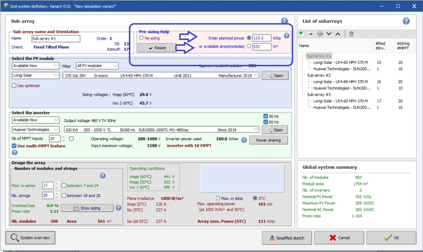
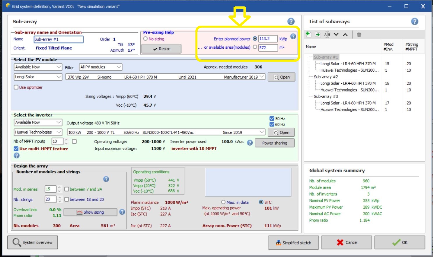
Hi, I asked this question 2 times and this is the third . Hopefully, I can get help from PVsyst team The problem as follows: For Grid-connected PV system, in "pre-sizing help" there are two options as shown in the figure First option: "enter planned power" Second option : "available area (modules)". Now let's assume that I want to install a PV system in specific location that have specific building area , Let's assume that I will choose the first option "enter Planned power" . My question is : How can I now that the entered power is suitable for specified building area ? in other words what is the relationship here between the area of the building and the entered Power?? Also , if I choose another option "available area (modules)" . this area is related to the area on PV modules which is not related to the area on the location based on that , How can I define suitable "available area (modules)" to be suitable for the building area ??
-
Hi, I have asked here in this forum a lot of questions , but unfortunately I didn't get any help or answer from PVsyst team or from other colleagues. Hopefully, I can get help for my question this time . Please can anyone explain to me this matter in PVsyst because I lost?? The problem as follows: In Grid-connected PV system, in "system window" , then in "pre-sizing help" there are two options as shown in the figure "enter planned power" and another option is "available area (modules)". Now let's assume that I want to install PV system in specific location that have specific building area as an example "3472 m2". Now in this case if I want to choose the first option "enter Planned power" . The question is How can I now that the entered power is suitable for this area ??? what is the relationship here between the area of the building and the entered Power?? Also , if I choose another option "available area (modules)" . this area related to the area on PV modules which is not related to the area on the location. How can I define suitable "available area (modules)" based on the location area ??
-
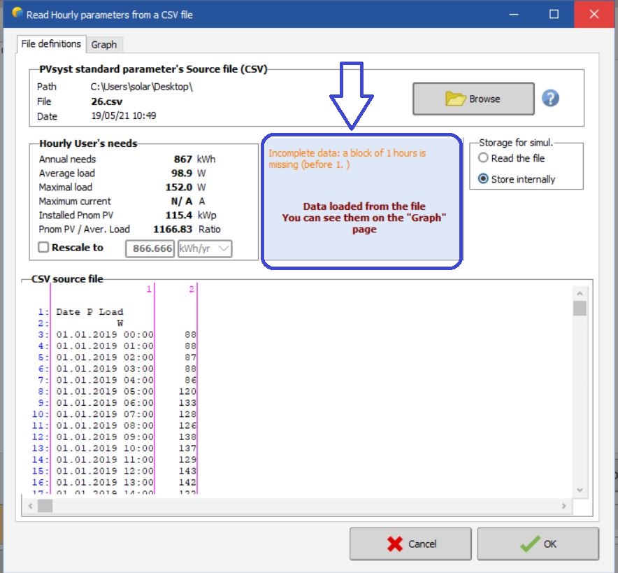
Hi, I have CSV file but I have problem when PVsyst reads the file as shown in the figure. I tried to follow exactly the instruction in the template provided in PVsyst but still the problem Can anyone help with this problem?
-
Thank you so much, but can you Please give further explanation about how I can define model them separately in 2 different variants.
-
Hi, How to calculate DC cable losses in PVsyst ?
-
Hi, I hope to get an answer for my simple question I want to design a PV system with two sperate fields with same orientation , the first field is 118.8 KW with100KW Huawei inverter and the second field is 74.7 KW with 60KW Huawei inverter. The design is meant for a factory which has two separate roofs but the load profile is for both roofs for that reason I want to design two parts with two different power ratings together. Is there any possibility to design such a system with two different PV and inverter powers in PVsyst ? Is there any possibility to get help please from PVsyst team or from other Colleagues
-
Hi, I have problem and really it consumed 3 days without solution , I hope to get any hint that could help me to find where is the problem. I have data consumption of customer in EXCEL , I converted it to CSV file , but the problem when I uploaded to self consumption section in the design , the system didn't read the file at all , I tried many times without success and I don't know exactly where is the problem because PVsyst don't notify about the possible error for CSV file.
-
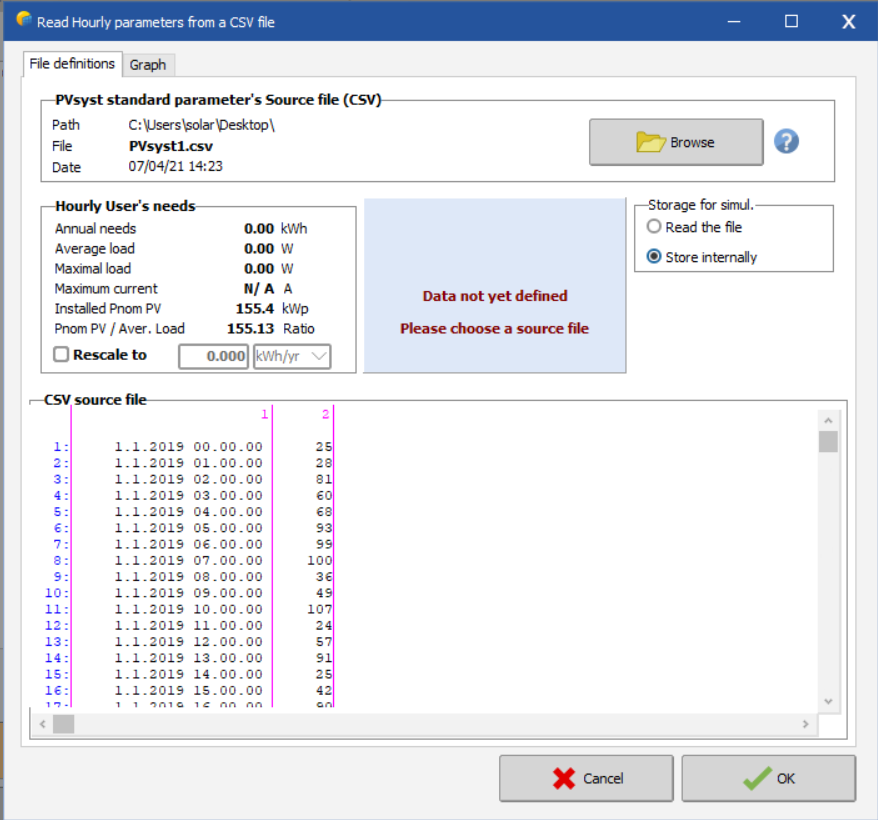
I have problem related to self consumption , I have CSV file and I tried to insert it in self consumption section but it shows me that it didn't success , I don't know why !! I have chosen the option *load values from a CSV hourly /daily file *, then I chose the option *choose CSV file* , after that a new window is opened with *browse* option to download the file, after that the values of CSV will appeared , but I got message *data not yet defined, please choose a source file* So how can I upload the CSV file in correct way ??
-
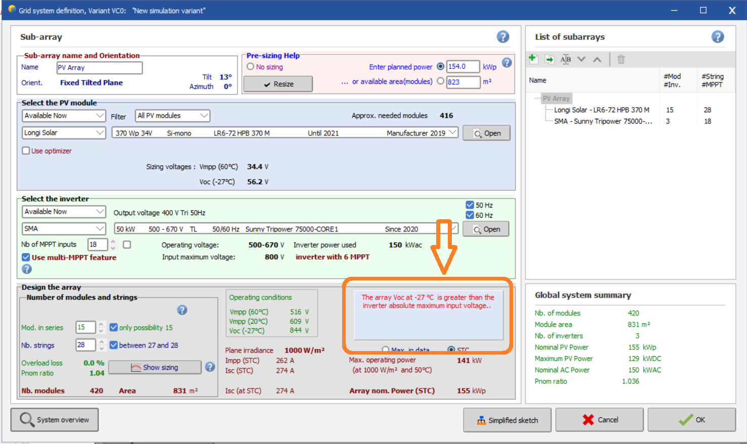
Hi, I have problem in my design but I don't know what is exactly the problem , the system consists of 154 KW DC power (Longi 370W PV modules) with 3 Sunny Tripower core 1 inverters of 50 KW (total 150KW). As shown in the error message " The array Voc at -27 is greater than the inverter absolute input voltage". the location of the design is located in Finland and in winter the temperature can reach until -30 , so I can't rise the temperature. When I tried to decrease the the number of modules in series , the system gave me error message "8 inputs with 1 string and 10 inputs with 2 strings , Consider disabling use of multi-MPPT feature for ensuring power sharing on each input" So , Can PVsyst team help me with any hint to solve the problem ?
-
Hi, Is it possible to design the grid connected PV system based on load profile of the customer in PVsyst?. I mean here , is there any option to insert the load profile for Grid-connected PV system design ?
-
Hi, I have small details about my design in PVsyst. I have PV modules power of 42.9KW with 2 Fronius inverters of 20KW each (with 2 unbalanced MPPT) , the design seems ok, PVsyst didn't give any error message. Now my question what does it mean "the small square" next to Mod in series and other next to No.string. Do these small squares have any meaning for the design ?
-
Yes , I have increased number of modules and the problem solved , thank you
-
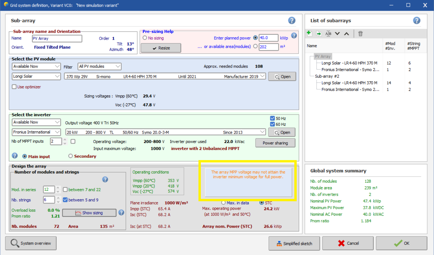
Thank you so much for the perfect explanation. Just I have small question related to my design , I have followed your instruction and the design seems to me ok but I have got message " the array MPP voltage may not attain the inverter minimum voltage for full power" , so does this mean I have problem in my design and how I can solve it ? Thank you for your Patience