azein
-
Posts
29 -
Joined
-
Last visited
Everything posted by azein
-
Should I conclude it's not yet possible to simulate such inverters?
-
I'm having an issue simulating an inverter with 4 MPPTs. The thing is that they are unbalanced, while when "Unbalanced MPPT" option is ticked in "Additional Parameters/Secondary Parameters" of the inverter, only two MPPTs can be defined. Please let me know how to simulate such inverters?
-
Dear, The project list is currently sorted by alphabetical order. But once the list grows, it becomes hard to find the needed projects. I believe that it would be great to have an option to sort the projects by modification date.
-
Dear, In the help file, at section "Pump-Model Description, Pump model from Ip and FlowR as f(Head) with fixed voltage", you state that you are using the strong hypothesis that Pump Efficiency is constant when varying the voltage, with measured variations of the order of 15% for a given voltage range. Would you please let us know what mathematical model would you use for calculating the efficiency curves at different rotation speeds given only the efficiency curve at 50 or 60Hz?? Many Thanks,
-
Is there anyway to simulate AC Coupled off-grid systems: Grid-tied inverter + offgrid battery inverter?
-
Dear, Shouldn't LID losses be calculated in Stand-Alone simulations? I cannot see anywhere in the "Detailed Losses" where to define LID. Best,
-
Thank you Andre for the quick response. In this case, it means you are using the PVC insulation values from table B.52-1 of IEC 60364-5-52 and not XLPE, is that right? I understand this AC cabling tool is not meant to be used as a cable sizing tool, so probably that's why you do not offer to choose insulation type, ambiant temperature coefficient, cable grouping coefficient, but as a suggestion I think it may be helpful to add these 3 options in a drop list for a quick cable size estimation. About the voltage drop value, is it calculated from standard voltage drop tables (which are usually given for resistivity at 90 degreesC), or for resistivity at 50 degreesC ? Best wishes and thanks for the hard work,
-
Dear, In the new module you added to PVsyst lately, there is the possibility to account for AC losses, and PVsyst automatically detects the correct cable size. From my understanding, the cable sizes given are for Aluminium not copper, am I right? Also, can you explain how these wiring losses are calculated: fixed resistance value or temperature dependent? maximum current injection all the time or real current values used? cosPhi=1 or less? Best
-
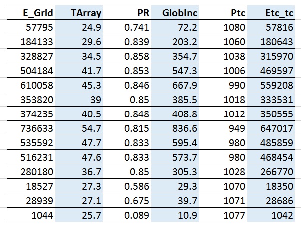
Dear, I'm trying to figure out how to reconstitute the PVsyst Egrid Energy output from the following PVsyst variables outputs: GInc, Tarray, Pnom, and PR my logic is the following: The Pnom corrected for module temperature is Ptc=Pnom*(1+gamma(Tarray-25)), gamma being the temperature coefficient of the modules The Egrid_tc should be equal to Ptc*(Ginc/1000)*PR This "logic" considers that the "PVsyst solution" is all incorporated in the simulated module temperature "Tarray". The following extract table shows PVsyst output data and the two formulas listed above for one typical day. I would like to understand why the first column and last column are not equal (Egrid calculated by PVsyst, and Egrid_tc calculated in excel using the above formulas). I made sure to use the temperature coefficient gamma given in PVsyst .PAN file (0.0041). Is there another correction to be done? Many thanks, PS: Reference for the formulas used can be found here: http://cleanpath.com/sites/default/files/pdfs/news/SolarPro_Managing_Risks_June_2011.pdf

-
I'm trying to simulate a Miasole CIGS thin film panel ( MR107). There is no available .PAN file in PVsyst for this panel, so I tried to import from Photon databese, but the import dialog box says: "There were some errors when reading the PV module data set." I also noticed that there is no "CIGS" in the list of technologies in the "definition of a PV module" Please advise whether it is currently possible to simulate such a module. Best regards,
-
While making different variations for a big project, with a complicated string setup (cannot be set with the "auto attribution"string) , I noticed that it is currenty not possible to "Load" a module string layout definition from another variation. Enabling this possibility would be very helpful, especially if you implement a variation comparison function as you said. I would also like to draw your attention to the fact that printing the Module layouts, the maximum papers printed are 2 papers, and thus if there is a big number of PV sheds, they don't fit. A solution I had found was to print on A0 papers, the maximum paper prints is 2, but it enables the print of more PV sheds. Best regards, Adnan
-
It's the same orientation for all the modules, but I have to shift some raws half a panel length so that it fits As for redefining the planes as independent rectangular areas, it is true I can do that. I would like to suggest that you add a "multi--selection" tool in the 3d shading, and a "grouping" tool, so that for example we can draw one part and then copy paste it elsewhere, but I think it would be a waste of time to develop complex drawing functions now, especially if you are planing to integrate a sketshup import function... That would be great, thanks for all your efforts, Cheers
-
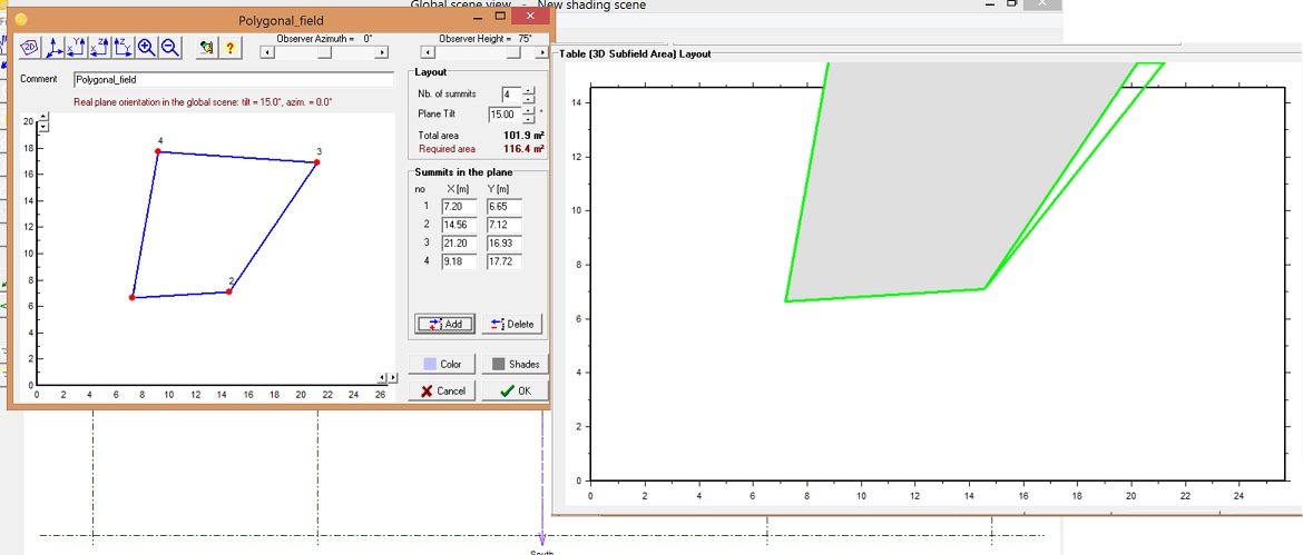
Well, actually the latter problem mentioned seems to be more complicated than just positive/negative coordinates. As shown in the image below, the polygonal field is not correctly translated in the "module layout" for any "large" field. If I stick to something lower than about 14mx14m in the first quadrant, the translation is done correctly. Once I go bigger than this area, the translation becomes wrong (does not fit into the screen, and the "grayed" area, where the modules are placed, is reduced)
-
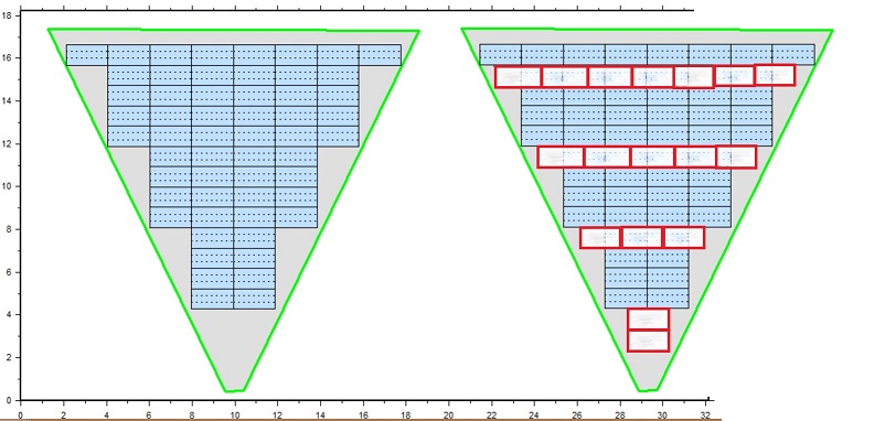
Hi, I am using polygonal field to draw a complex PV roof. By default, PVsyst arranges the modules as in the drawing below to the left. The way I want it is on the right hand side of the image below. I tried all the possibilities of "module Arrangements" in the "Module Layouts", with no success. Is it possible to have the modules as in the right image? Many thanks, Adnan ps. I noticed that if the polygonal field "summits" defined in the shading scene contains negative coordinates (X ,Y), then in the "Module Layout", the area of this field would not be correctly read. Defining only "positive" coordinates resolves this problem, but maybe you should give it a small fix. (2nd image as illustration)
-
You are absolutely right about that, PVsyst is really good enough, and I believe there are other upgrades that are more urgent than this. multi-heterogeneous orientations will maybe come later, especially that PV modules are getting cheaper and cheaper and so the perfect orientation is becoming less critical and installers will put PV panels on most of the available surfaces. As for the micro-inverters, it is certainly more appropriate on such systems, but honestly I haven't used micro-inverters on any of my projects. I should definetly do a cost comparison. By the way, how would you estimate the production of microinverters?!
-
Yes, that's how I was thinking of doing this simuation. Thanks But, if I can do it, why can't PVsyst do it? :roll: I'm not a programming expert, but I would imagine that a small piece of code would be able to dissicate a 20 orientations project on 10 inverters into 10 x 2 orientations project on one inverter, simulate those sub-projects one by one as per the current simulation code, before summing everything up. No offense meant :oops: Adnan
-
Dear, I would suggest to add a functionnality that would help compare different variations. It may for example tile up 4 variations per page, and listing for every variation important results such as total system production, specific production, installed power, nbre of inverters, tilt angle, ... together with view from the 3d shading scene for each variation. This kind of printout would really help comparing different possible layputs for a project. Adnan
-
Hi, I can manage to have one orientation per string. But I would also like to put 3 strings per inverter, and so I would have to have 2 orientations per inverter, with a 24degrees difference between the 2 orientations. Maybe I can dissicate the system and simulate only 2 orientations a time and then sum the energy production of all the simulations?
-
Hi, Do you think there is a way to simulate a dome shape PV system in PVsyst? (given that it will require multiple orientations connected to the same inverter?) If I only put 2 different orientations on the same inverter, would it be possible to make the simulation? Please advise on how you would do it. Many thanks
-
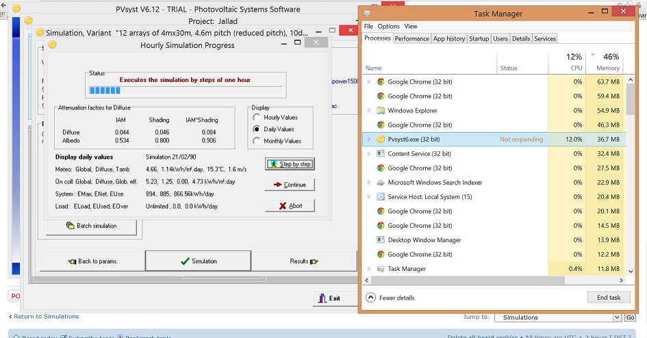
What do you mean by the whole "workspace"? What I'm doing is a project export (with all the components used), and then running the same simulation. I tried it now on a desktop with 2Gb RAM DDR2, 64-bit, intel CPU Quad @ 2.4GHz and it takes half the time it requires on my laptop with 4Gb RAM DDR3, 64-bit, intel i5 @ 1.8Ghz. (respectively 2m10s, 3m35s) What other information would you need to make the comparison? Adnan edit: I noticed that on my laptop (where the speed is slow), the task manager says that PVsyst is using 12% of the CPU, while in the detailed view (right click in task manager, go to details), it says it is using 25%. (photos below)
-
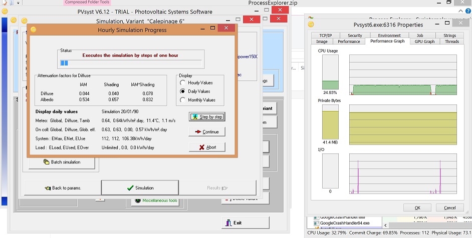
Salut Julien, I understand that improving the calculation times is a hard job, thanks for making the effort. But how can you explain that the same simulation goes like 3 times faster on another computer than on mine, while only 41Mb of memory is used by PVsyst all along the simulation(I usually have like 2GB free RAM available out of my 4GB total)? What can I do to match the speeds achieved by another computers? btw, I have an SSD hard disk, but I think that doesn't affect the simulation speed. Adnan resources usage
-
Dear Andre, All the simulations I do with PVsyst (I'm using version 6.1.20) use maximum 12% of the processor. With a detailed electrical shading calculation, it usually takes me an hour or so to complete the simulation. Is it possible to increase the processor usage in order to accelerate the simulation? Best regards, Adnan
-
Just one parallellipepede is like putting a wall. I'm not sure I understood your recommendation well...If I want to represent a 2m high fence 10cmx10cm, 10m long for example, and only one array to estimate the loss on one array before extrapolating, is it what ou recommend to put 200/10=20 parallellipepede of 10m one on top of the other? What about the CPU usage?
-
Hi, I'm trying to simulate a 5cmX5cm fence, 500m long! I tried simulating the real fence on a 10m distance, waited for the shading factors simulation 2days but it did not finish so I stopped it. What would you recommend? edit: the CPU usage by PVsyst during any simulation I do is always limited to 10%/12%, even if I give it a "high priority" in window's task manager. Is there a tweak for increasing cpu usage to, say 80%? thanks
-
Thank you,