AKSolar
-
Posts
11 -
Joined
-
Last visited
-
Is it possible to model trackers where the individual tracker rows are out of phase with each other?
-
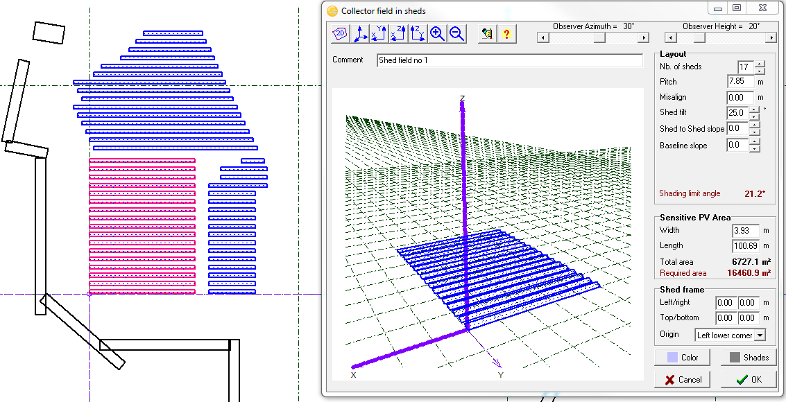
It seems that PVsyst is calculating the GCR using the the actual panel width, regardless of tilt angle. Wouldn't it make more sense to use the width from a top-down perspective, taking into account that a higher tilt angle shortens this width? Additionally, the Optimization tool used the term "Active Area Ratio" but this is never defined. Is this the same as GCR?
-
When you add DC Optimizer, the slider for separating strings into Orientation 1 & 2 disappears. This gives an error and prevents simulation. Is there somewhere else you can input this info.?
-
Go into "Albedo - settings" and look under "Other design parameters" under the "Design conditions" page.
-
Hi Bruno, Any tips on adding the space to the first line of the file? Not sure what program to use to edit the TM2. Thanks!
-
Awesome! Thank you for the fast turnaround!
-
Any tips on uploading Solar Prospector data for a specific year? I download the data as TMY2 format. The extracted filename looks like this: radwx_118153395_1998~.tm2 Now when I go to import this in PVsyst, I get the following error: Conversion error of string "-" => Integer Then it says: The file "radwx_118153395_1998~.tm2" is not a valid US NREL-TMY file(invalid first line) What seems to be the problem here?
-
I am experiencing a problem when I am trying to complete the Module Layout section. I label the tables under the "Comment" field in the 3D structure section. When I go to the Module Layout section, after clicking "Get From 3D Shadings" the drop-down menu still does not reflect the correct table names. In fact, the same table names are repeated up to 3 times in the drop-down list. I have tried creating a new project with this .shd file but still the incorrect names follow. I really do not want to re-create the shade file. I have added a couple screenshots to this post.

-
I am trying to model a system with 12,969 modules among 6 inverters. About 20% of the modules are 305W and the others are 300W. As you can see this does not break down evenly onto a single inverter, so one inverter will need to have 2 different module ratings. This does not seem to be possible with the multiple sub-systems feature. How could I model this scenario?
-
In computing the ground cover ratio as well as the 3D Module Layout it appears as though PVsyst draws dimension data from the module .PAN file, but these dimensions are not altered for a tilt angle. For example, a 4m wide module at 25° tilt would only be 3.625m wide from straight down. This provides a difficulty when trying to fit modules into the Table size you have established in the Near Shadings construction. The do not all fit. This also throws off the ground cover ratio.
-
It is a pretty standard arrangement these days to have copper string wiring and aluminum conductors from comber boxes to inverters. Is there a way to specify different materials for the different sections?