All Activity
- Past hour
-
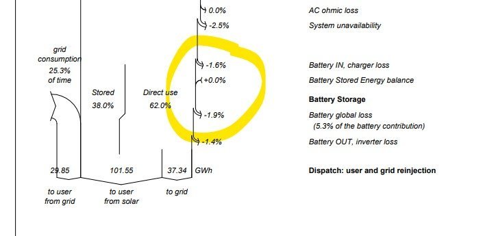
First of all: the value 1.9% is related to the total energy flux of the system. The real "round trip" efficiency of the battery pack should be related to the energy passing through the battery. This is mentioned as 5.3% here. I don't know where your affirmation of 85% comes from. This is extremenly fluctuating according to sources. Some Li-Ion battery manufacturer mention 95% on their datasheets (which is probably not realistic), others 90%, rarely less. Due to the extreme complexity of the battery model, especially the SOC evolution according to the charging/discharging balance, the determination of the battery efficiency cannot be quite reliable in the PVsyst simulation. This issue is fully explained in the help https://www.pvsyst.com/help/physical-models-used/batteries/battery-model/battery-efficiency.html?h=battery+efficiency
- Today
-
Dear PVsyst Team, We have a question regarding the battery losses displayed in the simulation output. The BESS loss parameters in PVsyst appear to reflect only certain categories of losses, and in our case, the "Battery Global Loss" is shown as approximately 1.9%. However, since the round-trip efficiency (RTE) of the battery is around at 85%, we would expect the total battery-related loss to be closer to 15%. Could you please clarify why only 1.9% is reflected in the simulation report? Is there a reason the full impact of the RTE is not shown under the battery loss section, or is it accounted for elsewhere in the system losses? Appreciate your guidance on this matter.

-
 Ady joined the community
 -

How do module dimensions in PAN file affect outputs?
exceptclay replied to shri's topic in PV Components
Geometry Dash Scaling module dimensions in the PAN file does not directly affect energy output—it mainly affects shading calculations and layout visualization. Energy yield depends on electrical parameters, not physical size. In contrast, specifying collector band width (used in 2D shadings) does influence energy results, as it determines how much of the collector surface is exposed or shaded, directly affecting irradiance and losses. -
exceptclay joined the community
-
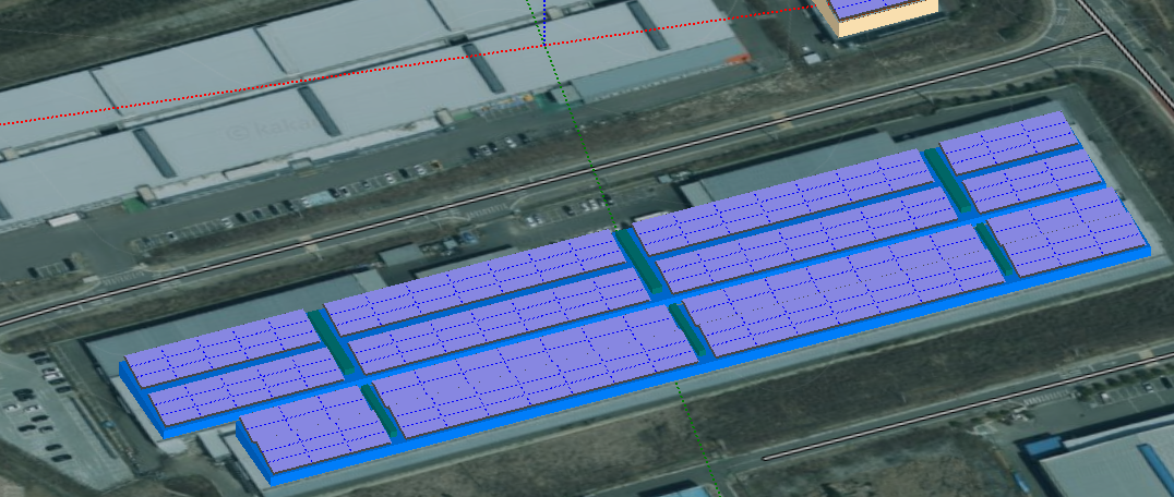
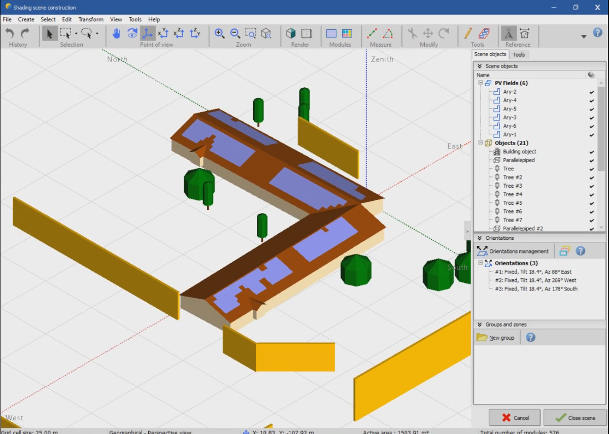
Good morning PVSyst team, always thanks for a solution.. For dome project (attached image of 3d scene), It seems really difficult to adjust bifacial system for it. An error message said, "tables width are not same" or this system is not suitable for bafacial system. Is there anyway i can reflect bafacial system for this proejct? I'm also considering to run pvsyst individually but even i did it the same error message comes out. Pls guide me, thanks
-
 Manoj Chaulagain joined the community
 - Yesterday
-

the influence of array pitch on the temperature of PV module
Auriane Canesse replied to Chen's topic in Simulations
Hello Chen, We did not carry out dedicated studies on how array pitch affects the heat dissipation. However, the thermal losses are indeed influenced by the PV module support structure and it affects the convective cooling on the back plane. The advised U coefficients corresponding to each structure type are described here: https://www.pvsyst.com/help/project-design/array-and-system-losses/array-thermal-losses/index.html#u-value-determination It is also possible to measure the U coefficient values for your installation as explained here: https://www.pvsyst.com/help/project-design/array-and-system-losses/array-thermal-losses/u-value-measurement.html -
Daily generation profile Irregularities
Auriane Canesse replied to JamesLenton's topic in Problems / Bugs
Hello James, If the dip in irradiance is not due to missing data, I would need your files to look into this issue in more detail. Could you send your project at support@pvsyst.com ? Auriane -
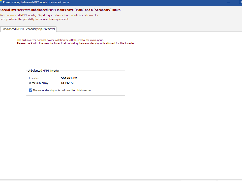
Dear Oli, Unbalanced inverters are not designed for power sharing. Regards,
-

Daily generation profile Irregularities
JamesLenton replied to JamesLenton's topic in Problems / Bugs
Hi Linda, We tried PVGIS and Meteonorm and saw similar anomalies on different days also. Weather data imported from those 2 sources shouldn't have missing data however? James. -
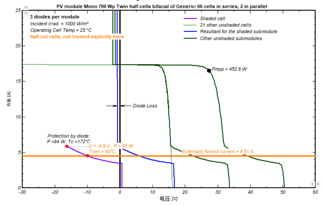
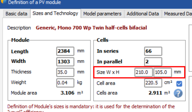
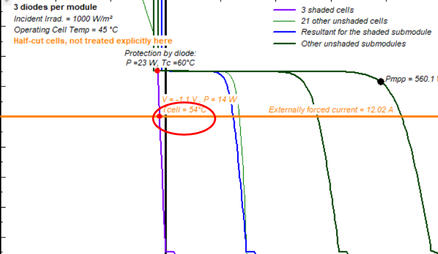
sorry ,i find a mistake in my sentence,the solar size is 210mm*105mm,so final result is 44/ ( 0.21*0.105*29) =25 = 94 (℃).The results are basically the same as those of pvsyst.
-
just choose "Generic_Mono_700W_Half_Bifacial.PAN" for example. Here, Uc = 29 W/m²·k, or say Uc = 29 W/m²·℃, and the size of the cell is 150 mm*210 mm. For one solar cell shading, if the temperature rises by 1 ℃, it need power 0.21*0.15*29= 0.9135(W),and the cell power consumption now is 45W,45/0.9135= 48.17 (℃),by adding 25 ° ambient,the result is 73.16(℃),which is not quite consistent with the results shown on the graph (95℃).Can you help me check if there are any errors in my deduction? thanks
- Last week
-
 Pedro Silva joined the community
 -
 Kadam joined the community
 -
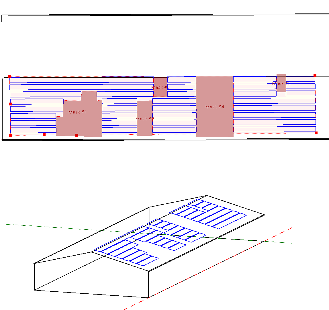
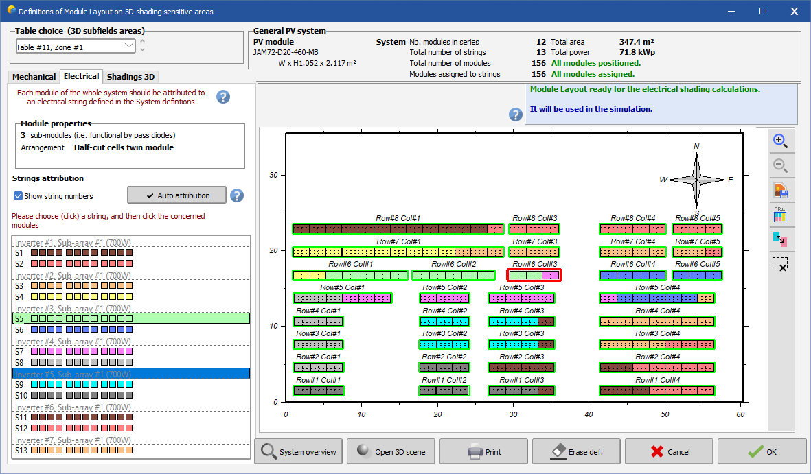
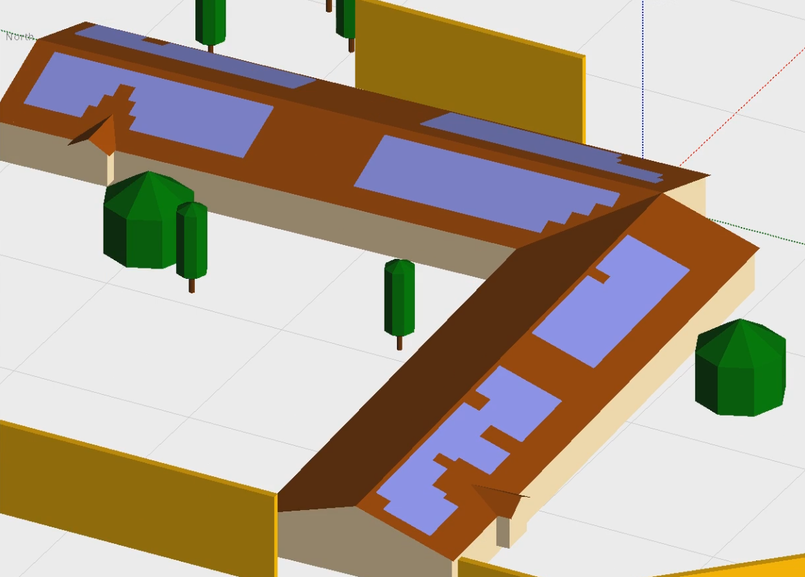
 I don't have any the details of this system and haven't modeled solar edge in a long time. However, with a zone you can auto set table to fill the zone, auto tilt to adapt to slope of roof, set table size to 1x1, and then use module layout for allocation (electrical loss). Keep in mind this is just for shading calculation, not power, so you don't need it perfect. As long as it is reasonably close to capturing the shading conditions it should be fine. You create a single zone, insert masks, auto fill the zone as shown. This will allow you to model bifaciality.
-
 Hi dtarin, thanks for the input. I can make a zone in a similar shape as the polygonal field, but when defining the Zone's Field Properties, I can only do a singular rectangular array - are you suggesting that I would have a bunch of little zones where I would need to align / elevate and line up each one in order to mimic the flush to roof mount shown above? The other factor that might complicate this the client wishes to use SolarEdge for this layout - not sure if using the zones in this manner would not be advisable then - ie defining the Module Layout's strings per inverter? Thanks again for the help and insight, much appreciated!
-
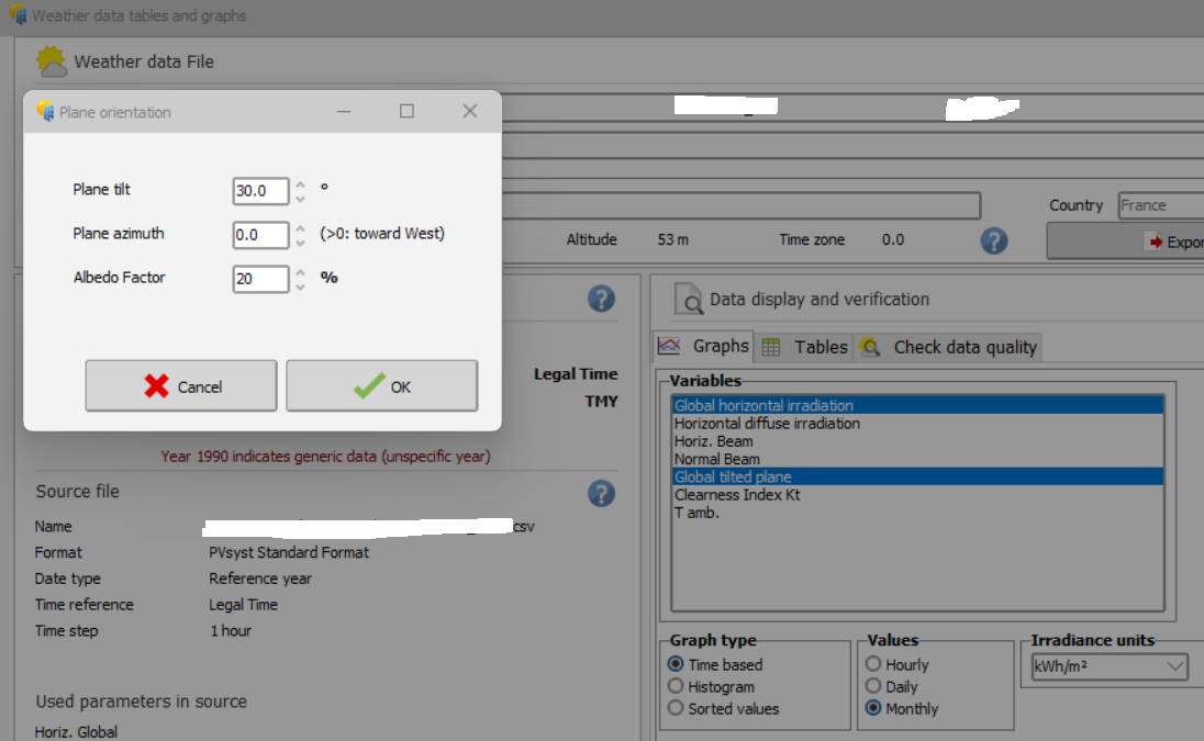
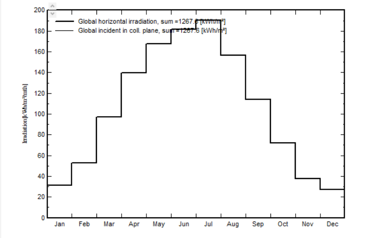
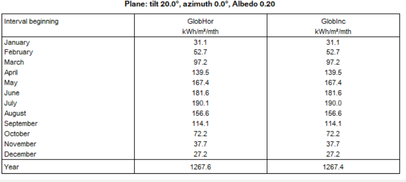
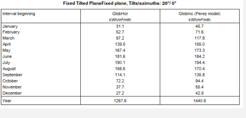
Hello, When working with a normal ground-based project, in "Weather data tables and graphs" , in both "Graph" and "Tables" tab, when I try to check for the monthly values of GHI and GTI, very often I see both values are the same, which is weird. Also PVsyst asks me for confirmation of the Plane Orientation, which I have already defined in System. Only when I try to see the value in Hourly, then it displays correctly , and then go back to the monthly values in both "Graph" and "Tables" tab, they will be display correctly. Steps: 1. Try to see monthly data, PVsyst ask for plane orientation 2. Monthly GTI = GHI ?? 3. Same when seeing in Table 4. Only when check the data in hourly mode, it seems to "fix" the bug 5. GTI and GHI in Graph and Table now correctly displayed
-
You can use draw a zone in the shape of the area with PV tables that will allow bifacial computation.
-
In this tool, PVsyst tries to evaluate the temperature of the reverse-biased cell, as a function of the power consumed in this cell and the U-value (with resp. to 25° ambient). In this case this is not dangerous, but in usual modules the cell temperature may become very high: this is the hot spot problem.
-

Trackers rotation axes when Azimuth is different from 0°
AdelB replied to AdelB's topic in Shadings and tracking
it worked. thanks for your quick reply. -

Trackers rotation axes when Azimuth is different from 0°
Michele Oliosi replied to AdelB's topic in Shadings and tracking
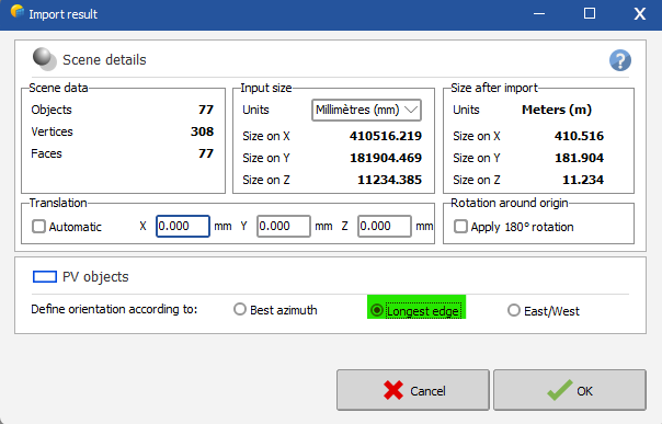
When importing, you should have multiple choices to define the orientation: Can you try "longest edge" ?
-
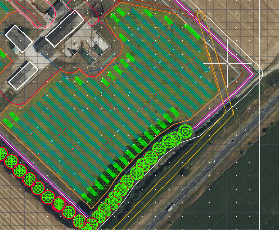
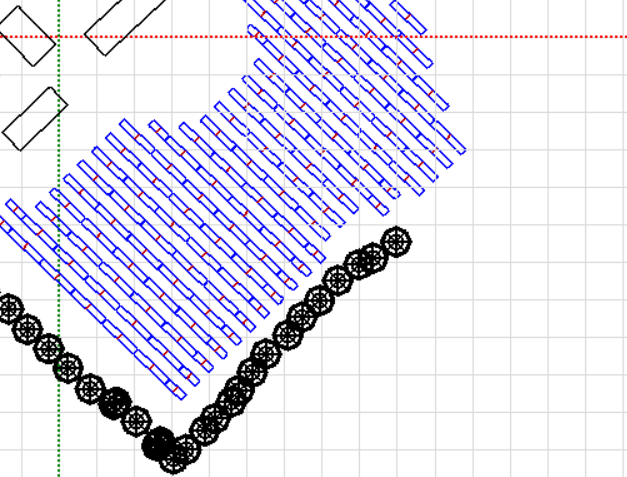
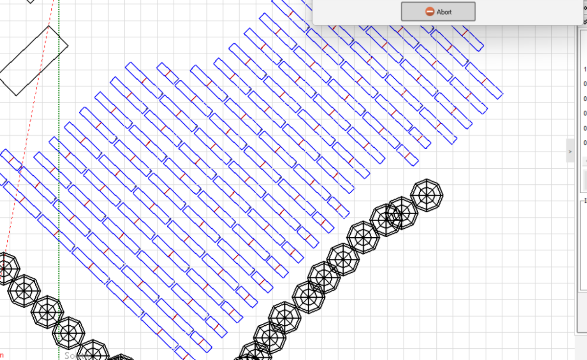
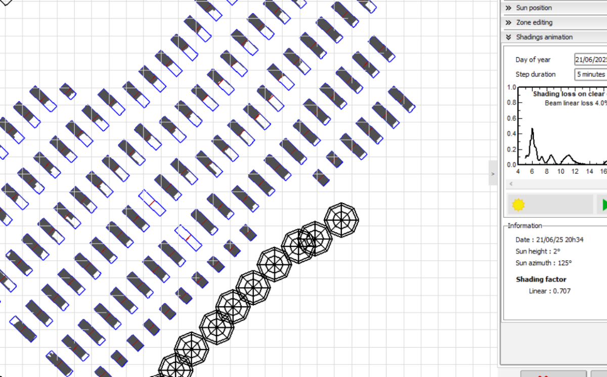
Hello PVsyst team, I am working on an Agri PV project where i have to respect the sense in which the crop is planted. Given that the crop is planted at -46.2°, i have to install my trackers accordingly. See picture below. The issue is that when I import the PVC scene on PVsyst and simulate the shading animation, the rotation axis used by PVsyst is N-S axis (as if the middle of the tables is the centre of of the rotation from south-east to north-west) while the intended rotation is supposed to be north-east -> south west) see picture below : (I'm putting the middel and the End of the simulation)
-
Finding out the reflection caused by the solar panels
Michele Oliosi replied to Adeline's topic in Simulations
The issue of reflection is that it is not explicitly modeled by PVsyst (currently). You should therefore find an indirect way to estimate it, or, better, find another tool that is more adapted. Also you interested in the reflection as a directional quantity? (for the purposes of glare regulations, for example). Or is are you interested in the amount of light “lost” to reflection, as a way to understand the energy flows? -
@Leticia Currently, albedo is still stored in the weather file as monthly coefficients. This means that the time series will be summarized into monthly values. The hourly time series will be exploited in a later patch. These coefficients can then be used in the project settings, but it still requires going to the project settings and click on the button to copy the values from the MET file. Since these coefficients can end up in the project settings, they are currently intended to be used for the far albedo.
-
Hello everyone, How to do power sharing for unbalance MPPT? I use SG50CX-P2 and 1 no. SG12RT. For SG12RT, I use 1 string per MPPT. During simulation error message show have to use all the main and all the secondary input and later I ticked the secondary input is not used for this inverter. but still I cannot so power sharing. How to do the power sharing for this inverter? Thank you in advance for your support.
-
in my opinion,the module VOC corrected by irradiance value and ambient temperature will be more reasonable for system design.
-
Dear PVsyst team: when some solar cell is partial shaded,how to calculate its temperature as shown in the following figure, thanks!
-
 shkim joined the community
 -
Hello Team, I am using V8.0.11 and trying to model Bifacial w/ Fixed Tilt Plane, Flush to Roof mount via Polygonal Fields - this is not compatible with bifacial 2D model - is this a bug or is there some way that I could model this irregular layout with bifacial (see snip of model)? I realize this flush to roof the bifacial factor will be very small, but the client is determined to confirm modeling this bifacial gain.. Any suggestions and thoughts are greatly appreciated, much thanks in advance! ie would converting to a Rectangular PV Array and trying to line up/match this jagged flush roof layout (as much as possible) allow the bifacial 2D model - or something else be a workaround? Thanks, Mike
-
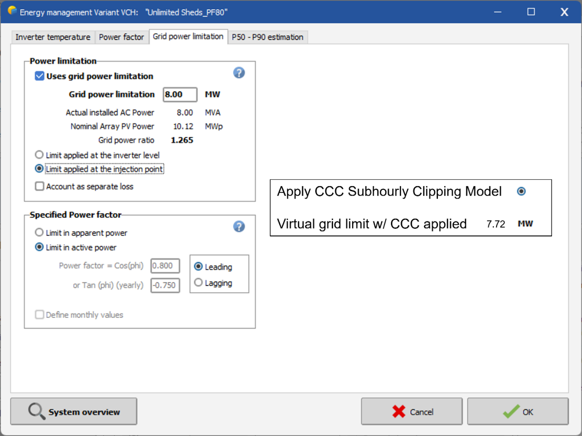
Here's one way CCC could be incorporated into PVsyst, to enable more accurate modeling with standard hourly TMY datasets: