All Activity
- Past hour
-
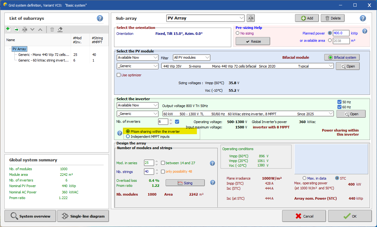
Dear Nikoloz, It seems that the inverter you want to use is a central inverter with only one MPPT. This means all strings connected to it must be identical. So, you don’t need to worry about the MPPT definition. In PVsyst, just select the configuration “PNom sharing within the inverter” (see below). Then, you only need to specify the number of inverters. Regards,

-
Dear Ishan, First of all, the Unlimited Tracker represents an idealized PV table layout, with all rows having exactly the same length. Most likely, your 3D scene doesn't follow this idealized representation. Could you please send us your project by email at support@pvsyst.com, so I can check it and explain why you're seeing these differences? Regards,
- Today
-
 Johann joined the community
 -
 Nikhil Pal joined the community
 -
 Steve_NO joined the community
 -
Hello I have such question. does anybody had used modular inverters ? Sungrow_SG1100UD what about this inverter ? when I uploaded OND file in PVsyst there is no information about MPPTs, there is some error with dtasheet ? I have to make desighn of 100MW plant but how to organise strings in mppts?? here is datasheet link https://en.sungrowpower.com/productDetail/4102/1-x-modular-inverter-sg1100ud-20
- Yesterday
-
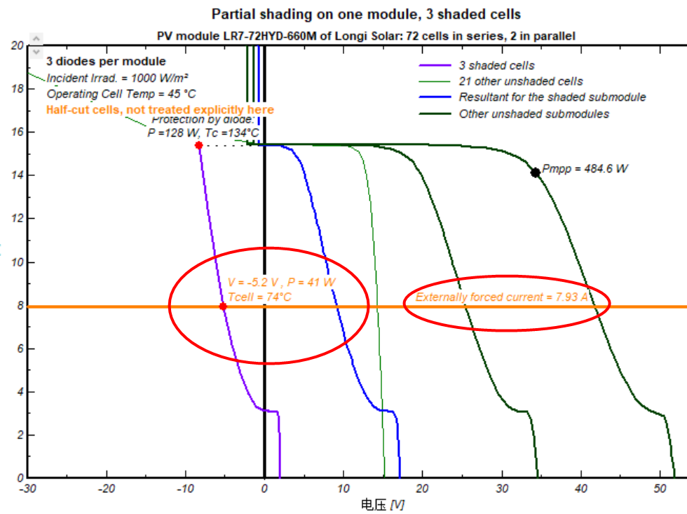
IRev is calculated according to the expression mentioned above, by neglecting Rserie (put Rs = 0). This expression gives the IRev as a function of a specified voltage. Iph is the short circuit current for this shaded cell.
-
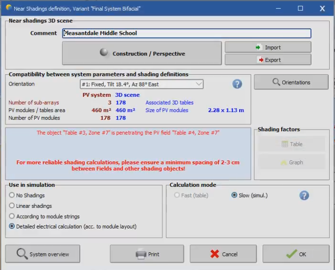
While simulating project with identical capacity, components, and loss factor , PVsyst has generated variable generation( E grid MWh) results for Unlimited tracker mode and the 3D scene mode . Egrid MWh Near Shading loss : Irradiance Unlimited Tracker 1438860 -1.8% 3D scene 1481095 -2.4 % I want to understand how PVsyst is generating variable results for Unlimited tracker and 3D scene mode which should not be case for identical project parameters(Pitch,1P,Other loss factors). What are the factors resulting in this variation .
-
OK IRev = Iph +aRev *V,for aRev=800mA/V^2, 800/1000*(-5.2)*(-5.2)= 21.632 (A) ;the externally forced current is 7.93A; how to calculate IRev? thanks
- Last week
-
 JORGE ELIECER CHACON F. joined the community
 -
 Vũ Thế Duy joined the community
 -
In PVsyst, the model for the reverse characteristics is this quadratic expression. This corresponds rather well to the reality, but this is a rough approximation. By the way the values of this model have a quasi null impact on the PVsyst simulation results. Now the term (Rserie * I) is indeed a little contribution (perhaps it should not be taken into account, we will check). You can forget it.
-
 If it still doesn't work you can always model it as I have above 🙂 The gaps will not matter for bifacial calculations, they are not used. The user defines the transparency factor manually which takes into account gaps in structure, modules, etc. So I'd either model as I have or increase the gap in your method if the suggestion above does not work.
 -
Select 'Disable field interpenetration check' from inside shading scene and see if that works
-
 Thana joined the community
 -

Finding out the reflection caused by the solar panels
Adeline replied to Adeline's topic in Simulations
Thank you for the fast response! is it possible for you to share some ways to indirectly estimate? Yes! I am looking for the purpose of glare regulations -
Excuse me, Prof.Andre Mermoud is I the reverse current in this formula,so a more accurate representation would be IRev = Iph +aRev *(V+Rs * IRev) ;and the externally forced current is IRev? thanks for reply.
-
 Eylül Nazlı YAMAN joined the community
 -
You're a great help Jéremie! Thank you.
-
Dear User, In this case, please email us at support@pvsyst.com your PVsyst LOG files (menu <File> <Export logs>) so we can analyze what happened. Best regards.
-
Excuse me, but this problem happens with any project.
-
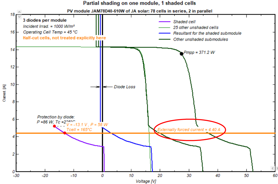
This tool shows what happens for a specified current (i.e. imposed by the rest of the string). You can drag the red point of this forced current for analysing what happens at different values. The voltage of this point is the result of the reverse characterisics model: You can find this formula in the help https://www.pvsyst.com/help/physical-models-used/pv-module-standard-one-diode-model/reverse-characteristic-of-a-cell.html The temperature is obtained by applying the U-value on this cell, taking the dissipated power as input parameter instead of GlobInc.
-
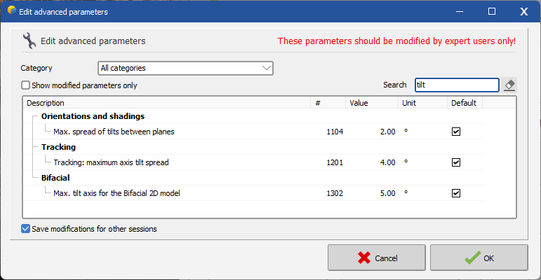
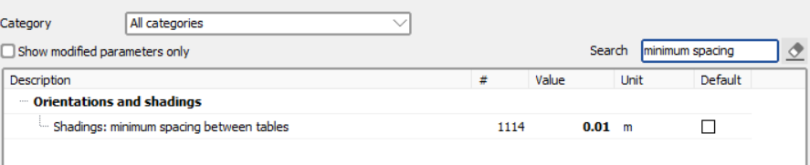
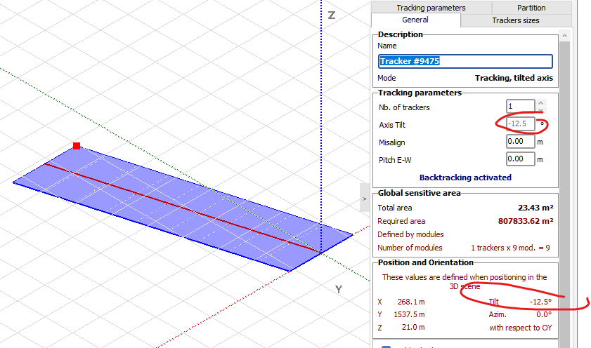
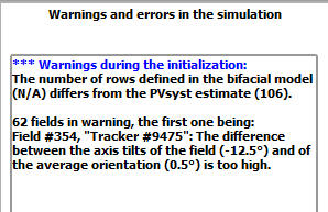
Hello, the difference between the axis tilt of the field and the average orientation it belongs to is higher than the default tolerance for this parameter. You can adjust this tolerance in the advanced parameters. To find it, use the search filter and type 'tilt'. The relevant parameter in this case is 'Tracking: maximum axis tilt spread'. You can set this tolerance to 13
-
 apiconnects joined the community
 -
as we can see the three values on the figure, the V (-5.2V),I(7.93A) and P(128W),Is there a formula that can explain their relationship,thanks!
-
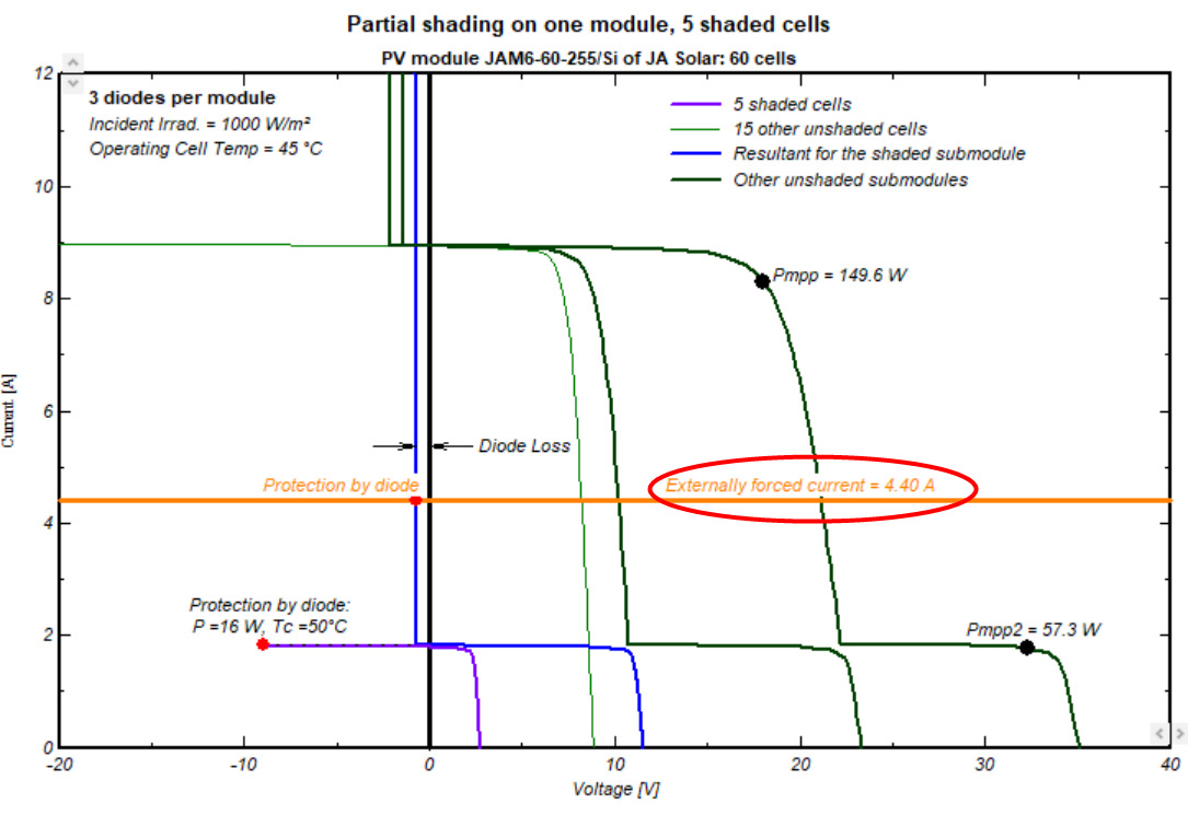
Dear pvsyst team: I am using this software to simulate the temperature and power when a cell is local shading. I find that “externally forced current= 4.4A” is all the same for the different solar modules. What does it mean? thanks!
-
 Hi dtarin, I updated that but I still get this error: Thoughts? Can I send over the project file for your take on it?
-
Try updating this.
-
Hi PVSyst Team, I already generated the PVSyst report and these warnings appear during initialization. The 3D scene comes from PVCase and a TFT. Can someone assist how to deal with these errors? Appreciate your help.
-
 Yes, that's correct. The site I was working with had the trackers tilted on the terrain with different tracker heights and axis tilts. The custom diffuse tracker that I had selected in version 7.4.8 worked with the selection of adjacent masking trackers. But after importing the project to version 8.0.9 the masking selection did not select the adjacent trackers and I had trouble getting that to work.
 -

Potential Bug in "Weather data tables and graphs"
Bruno Wittmer replied to Hung MAI's topic in Problems / Bugs
Thank you for reporting this problem. It will be fixed in one of the next PVsyst versions. -
Dear User, You can use PVsyst menu <File> <Export projects> to easily export your project files in a ZIP file and email it to our support address: support@pvsyst.com with your PVsyst LOG files (menu <File> <Export logs>) so we can analyze what happened. In the meantime, you can already read our FAQ about the most efficient way to optimize PVsyst simulation time: https://forum.pvsyst.com/topic/3542-how-to-optimize-simulation-time/?do=findComment&comment=9867 Best regards.
-
Good day! I have a 32 core processor but cant use it for full power( Every time when I try to turn on "Enable multi-threading" flag PVSyst stop working without any crashes. When I try to open any project its freezes in endless loading. When this option off program working well, but calculations calculations are sooo slow. How can I fix that?