All Activity
- Today
-
Hi, is there a recommendation for a Uc value for single axis tracker (N-S) with 1 modul portrait? Thanks
-
 I understand. What I mean is, if the irradiation intensity on the back of the module is relatively low while that on the front is relatively high, so does it imply that the low-light performance of the rear side is worse?
 -
 Yes, actually the irradiance of front side + backside*bifaciality factor are put together, which gives an effective irradiance evaluation. Only after that, the PV conversion model applies. Indeed, the light reaches the same cells, be it from the front or the back. The same low-light performance is therefore taken into account for front and back (up to the bifaciality factor).
 -
The temperature is generated from the monthly values saved in your site file, using the Meteonorm algorithm https://www.pvsyst.com/help/physical-models-used/synthetic-data-generation/index.html
-
Because the irradiance of the front side or the rear side of PV module will be different, in this case, there will be a difference in conversion efficiency between the front and back sides,with respect to 1000 W/m².
-
Thank you for your explanation. May I ask how the Tamb is generated?
-
thanks
- Yesterday
-

Quick orientation optimization (acc. to clear-sky model)
André Mermoud replied to Sydwell's topic in Meteo data
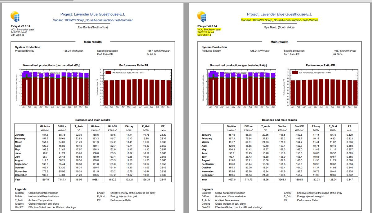
There is no automatic way of optimizing the system for summer or winter in PVsyst. You are probably thinking about the "Quick optimization" tool present in the "Orientation" definition dialog. This is just an "immediate" tool for indicating how your present orientation choice is situated with respect to the optimum for this period. This choice doesn't modify anything in your orientation parameters, and therefor nothing in your system definition. -
Dear sir: Has the software taken into account the low-light performance on the rearside of bifacial module? thanks
-
Good day, I have noticed that when I optimise my simulation for winter or summer, this does not affect the results and the results are the same as oprimised for annual yield. Might you advise what may be the issue. Best regards, S. Matolo

-
 Engr. Munir Ur Rehman joined the community
 -
 Antonio Carotenuto joined the community
 - Last week
-
Thank you! I will give that a try.
-

Modules following terrain slope in 3D shading scene
Jéremie Bernier replied to emily.denz's topic in How-to
Hello, to better assist you, please send the export of your project, including the problematic table name, to support@pvsyst.com -

Modules following terrain slope in 3D shading scene
emily.denz replied to emily.denz's topic in How-to
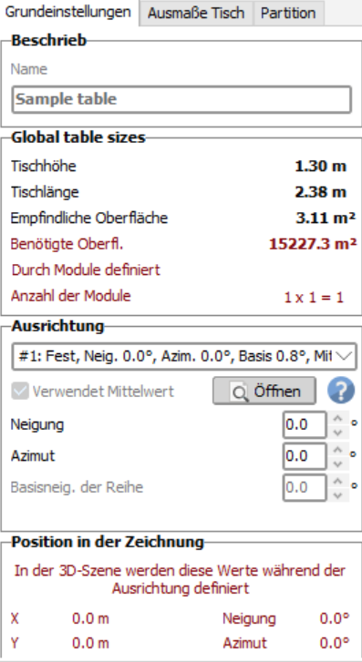
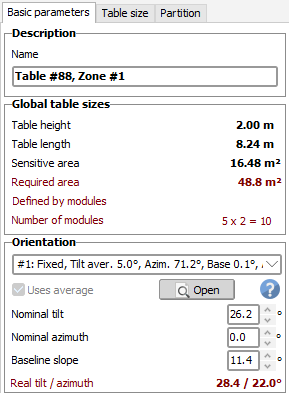
Thank you for your help. For some reason the Baseline slope is not adjusting, as you can see in the screenshot - I think that is the reason why it is not working. How can i change this?
-
 Trevor Turnbull joined the community
 -
 Engr. Usman Javed joined the community
 -
 ADAGE RENEWABLES joined the community
 -
 Bryan joined the community
 -

Turning on Bifacial when using 2 different module types of different size
Robin Vincent replied to Jig's topic in How-to
If you have only two types of modules in your system, you can still create two orientations. One to be used for all subarrays of the 1st type, the other for the 2nd type. These two orientations can have the same parameters, but it will allow you to setup your bifacial system with two module sizes. -
Actually I have 40 separate subarrays. 8 of them have one module type. 32 have the other. All share the same "orientation".
-
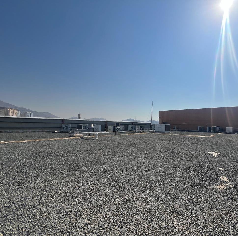
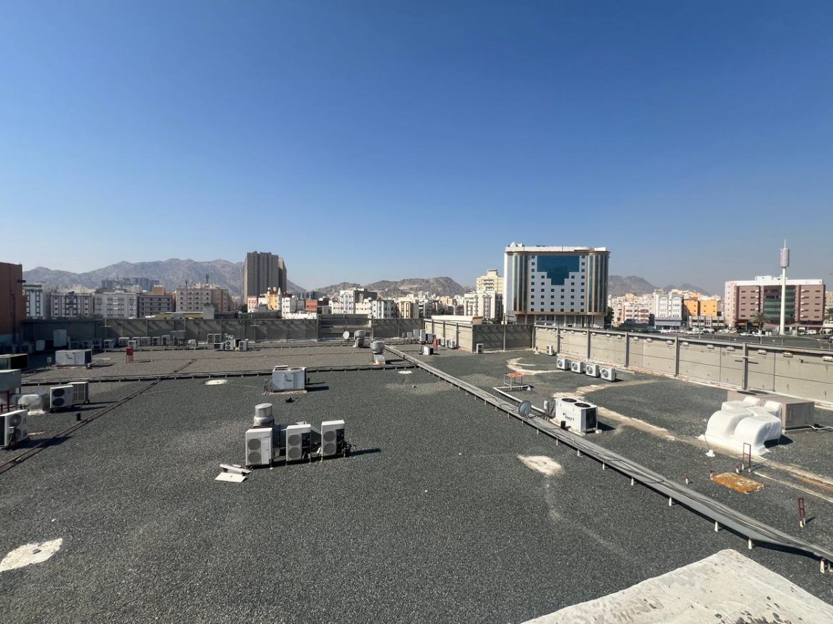
In one of our project sites, the rooftop surface is covered with gravel (dark-colored stone material). Could you please advise on the most suitable Albedo value to use for bifacial module simulation in this scenario? Kindly refer to the attached roof image for reference. Finally, please consider the effect on reflection, as it is a rough surface, not a smooth surface with one color.
-
 Mohammad Al-Hayek joined the community
 -
Modules following terrain slope in 3D shading scene
Jéremie Bernier replied to emily.denz's topic in How-to
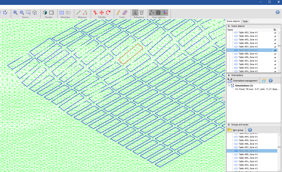
Hello, If you’d like to fill an area on a hill with PV modules, you can use the Zone Editing Tool. Once you've defined the zone using either a rectangular or polygonal area, click on Field Properties and set the desired tilt and azimuth (select Uses average), then click on Fill Zone. Here’s an example of how a filled zone appears on hilly terrain: After filling the zone, you can select and edit an individual table (like the one highlighted in the scene above). You’ll notice that the baseline slope is automatically taken into account. The Basic Parameters of the selected table will also show the actual tilt and azimuth values for that specific table: Hoping this helps you.
-
This is probably due to a bad definition in the PAN file used. I have corrected / securized this problem for the version 8.0.15, to be released mid-august 2025.
-
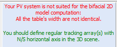
Regularity is defined vaguely by PVsyst. If the system is approximately regular, e.g., patches of trackers or tables that are more or less evenly spaced, then this can be considered “regular” in the PVsyst sense. In that case, you can use the 2D bifacial model jointly with the 3D scene. PVsyst will check the following points: The RMSD of the pitch distribution. If the RMSD is too large, PVsyst will throw an error. You can change the threshold of the error in the advanced parameters. Whether the tables are the same height. If there are differently tall tables, PVsyst will throw an error. Whether orientations have more than 2 rows. If there is only one row of tables, PVsyst will throw an error. The average axis tilt of the trackers in each tracker orientation. If the average axis tilt is too large, PVsyst will throw an error. You can change the threshold of the error in the advanced parameters.
-
Turning on Bifacial when using 2 different module types of different size
Robin Vincent replied to Jig's topic in How-to
The issue lies in the fact the bifacial model is linked to the subarray orientation, but the modules information are from the subarray. I guess from these messages that you may have two subarrays with different modules sharing the same orientation. One easy workaround would be to define two identical orientations, and set one to each of your subarrays. The main drawback of this solution is that your two subarrays won't cast shadows to each other on their rear sides (since the "unlimited" model used for the rear side is only considering mutual shadings). -
Is it impossible to apply the rear system for modeling that is not arranged regularly? I want to apply double-sided efficiency when installing solar power on the ground But solar 3D modeling on the ground can't be represented in a regular arrangement
-
Currently, the rear-side model of irradiance is two-dimensional (cross-section). However, it is compatible with a 3D drawing. If you have a 3D drawing with a regular arrangement of tables, you can activate the 2D bifacial model to compute the rear side irradiance.
-
Hello, In my project, I’m working on the shading construction and I’ve imported a 3D map to simulate a ground-mounted PV system on a hill. I would like the module tables to lie flat on the ground, following the slope of the hill. However, when I set the tilt angle to 0°, the modules are placed vertically. My intention is for the modules to be flush with the terrain surface—meaning their tilt should automatically adapt to the slope of the ground at each point. How can I configure the system so that the modules follow the terrain slope correctly? Thanks in advance!
-
Hello In the case of using two-sided modules these days, there is an issue about calculating the efficiency of the back and adding it to the module capacity. As far as I know, the efficiency of the double-sided module is applied only to the 2d model, but is there any way to simulate the power generation time by applying the double-sided efficiency in the 3d model?
-
 I have a few sites where I get an error message stating: This will NOT simulate unless I select "Don't use in the simulation" under the Bifacial Model. Is there anyway around this? Thanks!