


Lunatic09
-
Posts
6 -
Joined
-
Last visited
Posts posted by Lunatic09
-
-
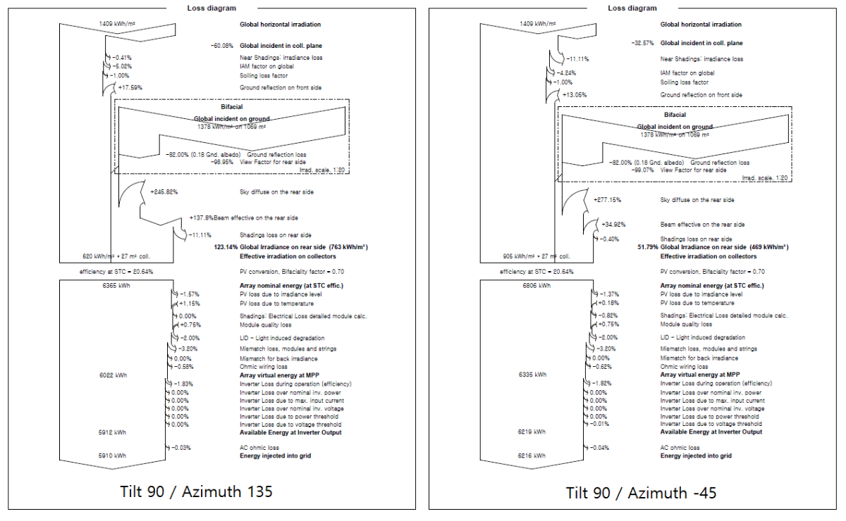
I simulated bifacial PV system with tilt : 90 degree, Azimuth : 135 / -45 degree (same position but facial direction different)
I set the parameter of back shading of azimuth 135 degree to near shading loss value(obatained from 3D simulation) of azimuth -45 degree.
The opposite case was carried out in the same way.As comparing the results (attached image), "shading : Eelctrical loss detailed module calc." looks the loss only effected by the near(front) shading losses.
In case of back shading loss is high and near shading loss is low, value of "Shading : Eelctrical loss detailed module calc." is low. (left loss diagram attached image)
Q. How can I apply the electrical loss caused by back shading ?
-
Thank you for your response.
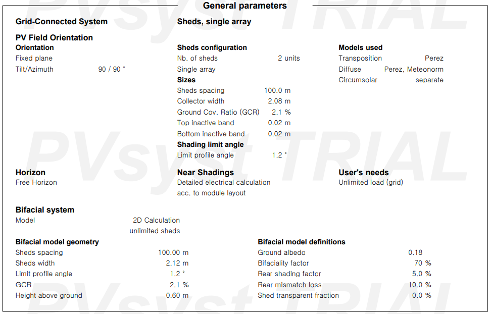
I simulated vertically installed bifacical pv system without any shading objects.
[Simulation Conditions]
PV module tilt : 90˚ / azimuth 90˚ (Faced west side) / shed distacne 100m (for eliminate interference between modules)
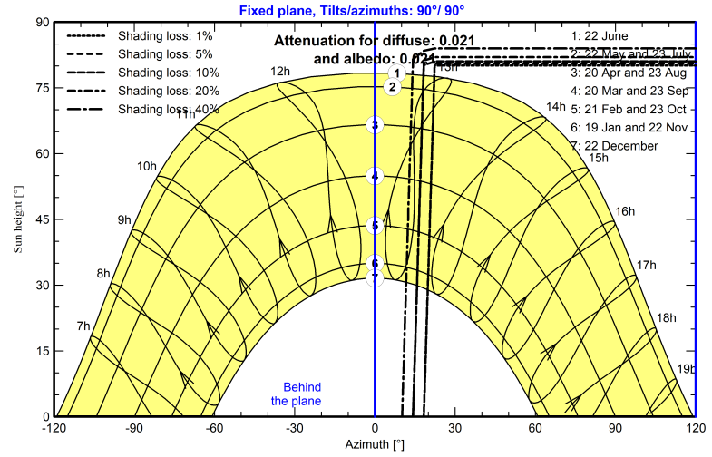
Even if there is no shading objects around PV modules, there is shading loss around 10~20˚ Azimuth.Could you explain me why those losses occures?

-
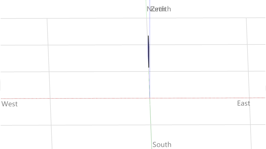
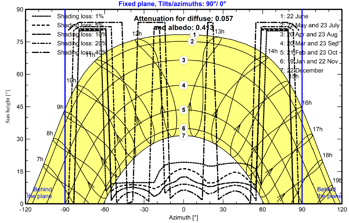
I've tried to simulate vertically installed bifacial PV system(Tilt : 90 degree, Azimuth :0 degree).
I have a few questions about iso-shading diagram(attached image file)
1. Why there is each persentage(1%, 5%, 10%, 20% and 40%) of shading losses? and what does it mean?
2. Is the shading loss mixed direct shading and diffuse shading? if it mixed, is there way to seperate the direct and diffuse shadings ?
-
Thank you for your response,
Do you have a plan to support a hourly data output of Probability ?
And I tried mixed orientation system setting, I can only adapt mixed #1, #2 but other #3, #4 can't adjust
If I have 4 mixed orientations, how can I set up 2 inverter with #1,#2 and #3,#4?
Should I simulate project separately ?
Can I also simulate two differnt type of modules with 1 inverter ?
Thanks,
-
Q1 Is there any way to achieve the power generation data of probabilities such as P90, P70
Q2 How to connect arrays with different tilt and azimuth to 1 inverter ?
Shading : Electrical loss detailed module calc.
in How-to
Posted
I simulated bifacial PV system with tilt : 90 degree, Azimuth : 135 / -45 degree (same position but facial direction different)
I set the parameter of back shading of azimuth 135 degree to near shading loss value(obatained from 3D simulation) of azimuth -45 degree.
The opposite case was carried out in the same way.
As comparing the results (attached image), "shading : Eelctrical loss detailed module calc." looks the loss only effected by the near(front) shading losses.
In case of back shading loss is high and near shading loss is low, value of "Shading : Eelctrical loss detailed module calc." is low. (left loss diagram attached image)
Q. How can I apply the electrical loss caused by back shading ?