


cliebner
-
Posts
4 -
Joined
-
Last visited
Posts posted by cliebner
-
-
Hi,
From my perspective, I would like to have confidence that pitch is maintained between rows as I adjust the ground slope. During construction, rows will be installed with the specified spacing, as measured over the ground regardless of slope.
From a little playing around in PVsyst (v6.48), it appears that the shed-to-shed slope method DOES maintain pitch.
However, if you use the Ground object and Zone method, be sure to define the pitch as 'cosine(slope angle)'. It seems that this may be because the Zone is defined and filled out in the x-y plane, so the pitch value that you enter to fill out the zone is actually the projection of the sloped pitch onto the x-y plane.
See attached images.
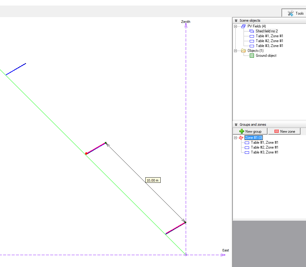
In my exercise, I created a ground object with coordinates (0,0,0), (0,20,0), (20,0,20), (20,20,20) (a -45 deg slope), and used the Fill Zone tool to create a field of 2 tables.
Next, I created a PV shed object, defined a -45 deg shed-to-shed slope, and positioned it on top of the tables in the ground zone.
PV modules for both the ground zone tables and the sheds have the same length-width dimensions and the same plane tilt.
Image 1: x-y view of the shed (pink) and zone tables (blue), with the measuring tool showing 10.0m between zone tables in the x-y plane.
Image 2: x-z view of the shed (pink) and zone tables (blue), with the measuring tool showing 14.15m between zone tables along the ground plane. cos^-1(10/14.15) = 45 deg
Image 3: x-z view of the shed (pink) and zone tables with new pitch defined as 10*cos(45 deg) = 7.07m (blue), with measuring tool showing 10.0m between BOTH sheds and zone tables.
Maybe this is obvious to everyone, but it took me a test simulation to figure it out. :)

1) x-y plane: sheds in pink
2) x-z plane: sheds in pink
3) x-z plane: sheds in pink with corrected zone tables
-
I was able to run a batch simulation of varying panel tilts with sloped ground without error by removing the constraints in the Preferences section / Edit hidden parameters.
-
Hi, I believe I have the same issue as the original post.
Using PVsyst V6.43:
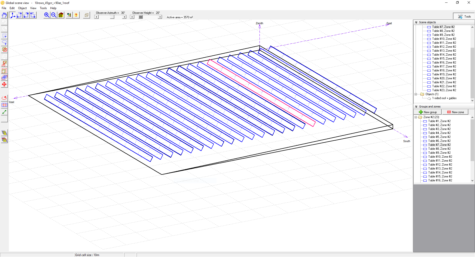
Created one variant with PV sheds at fixed tilt 60 deg, 90 deg azimuth (aligned N-S), and positioned on a 1-deg sloped surface.
Would like to run batch simulation only varying the fixed tilt (same weather file, same module layout, same sloped surface).
However, for any simulation with a tilt angle that does not match the tilt angle in the variant definition, I get the error message: "Error: The orientation of the collector plane for shadings doesn't match the one defined in the "Orientation" parameters of the PV array"
As the original post mentions, there is no problem running batch simulation varying only the panel til when the sheds are positioned on a flat (0-deg) surface.
Should I use the Ground construction tool to create the sloped surface instead? Is there a better way to use batch simulation of varying panel tilt angles on a sloped surface?
Use case: hourly results from all simulations serve as a large look-up table to determine "best" tilt angle at every hour for the weather data used in the variant.
Thank you for your time.
my near shadings construction


Downloading and Importing from the new NSRDB Viewer
in Meteo data
Posted