


Lockyy
-
Posts
14 -
Joined
-
Last visited
Posts posted by Lockyy
-
-
Anybody from the PVsyst can answer this? I tried the tool Electrical behaviour of PV arrays for th version 1) and it showed me for the shadow of 20 submodule (1 diod), that the U_Mpp is already close to the U_MPP-range. If 40 submodules are shaded (2 diods), the U_Mpp is already out of the U_Mpp_range.
If I have version 3), the maximum shaded submodules would be 15, so everything within the U_Mpp_range. So I think it is definitly the better version!
Can somebody from PVsyst answer me?
-
Yes, the lowest current drives the current of the string, so in #3, when the bottom modules are shaded, the entire string has reduced output. The according to strings method of shading will capture this effect for c-Si modules (setting electrical effect to 100%).
For 3:
When the last module is shaded, the MPP-Tracker will finde same current at a different voltage and skip the modules. So IF the rest modules have enough voltage to bring it to the mpp-range, I lose 20 modules -> 1/4 of modules, the rest is normal.
For 1:
Same situation, I lose 1 string of 20 modules completly -> 1/4 of modules, the rest is normal.
It gets more complicated if I even consider the bypass-diods and only shading at the very bottom.
For 3: The string l lose 1/3 of 20 Modules (MPPT finds the MPP and skipps the last diods)
For 1: For the last string, IF 2/3 of the voltage is in the MPP-range, MPPT finds the MPP and skipps the last diods. -> I lose 1/3 of 20 modules
BUT: If 2/3 of the modules are shaded:
For 3: the string have the voltage of 15 full modules and 5 modules with only 1/3 of voltage, it is still possible to find the MPP and skip 2 bypass-diods each.
For 1: for the last string we only have 1/3 of voltage for 20 modules, so it will probably be outside the MPP-range -> I lose the string completely.
So in the end I have the MPPT and bypass-diods for finding the voltage with the "full" current. Or do I miss something?
In my opinion therefor it is better put only 5 shaded modules in one string each, so worst case you have 15 non-shaded modules with enough voltage. But I do not have english literature for this, just german one:
https://photovoltaikbuero.de/pv-know-how-blog/teilverschattung-solargeneratoren-teil-33/
If you have a solar generator, the modules that are occasionally affected by partial shading (eg by a tree or a tree) all in a module string summarize, so that it then a string with shaded modules and a string (or more strings) with the unshaded Modules exist. This is a question that is asked again and again. The answer is no ... and why it goes like this is explained in the following article. -
Hello,
I have a question. If I have rows of tables 4x20
More possibilities for the stringing:
1)Each row is one string:
_________
_________
_________
_________
2)Every two rows are one string:
_________ _________
_________| _________|
_________ _________
_________| _________|
3) Every four rows are one string
What are the number of strings in width and in height:
1)
width: 1
hight: 4
2)
width: 2
hight: 2
3)
width: 4
hight: 1
???
The simulation shows that 3) ist much worse than 1). But in reality in 3) for each string, only some module will be shadowed in the morning. But as I understood PVsyst, this is not how it works?
If the lower modules are shadowed in 3), the whole string is influenced!?
Can somebody enlight me?
-
If you are talking about DC ohmic losses, just enter the percentage you want to use. Click the cursor into the wire resistance field above after updating the percentage, and then click back below into the percentage field. The mOhm should update when you first click into it after updating the percentage.
Yes I know. But every time I change the system (less modules, more modules), the mOhm stays fixed and the percentage changes to 1.13% or 0.88%,...I want the percentages to stay fixed 1%.
-
Any ideas anybody?
-
Hello,
I am trying to calculate a project and want to compare different inverters and panels. But every time I change the system, the ohmic losess (percent) change. At this point I don't want to vcalculate cables or anything. Is it possible to keep the losses fixed to values like 1% or 1.5% and NOT xy mOhm? If not, is there a chance to make it possible in a future version of PVsyst?
Thanks in advance!
Lockyy
-
Hey,
I have a roof top with a tilt of 6°towards east and now I want to place modules with 15° south on it. Usually I import the modules via Autocad and then change the tilt but it always changes the angle of the former 6°.
I even tried to import a module with the correct angles but when I use "transform to PV faces", one of the two angles gets lost.
Please find attached a screenshot (sorry for my bad drawing skills...)
Any suggestions?

-
I made a complete new project with the same data and now it worked...I even used the same shading. Strange!
-
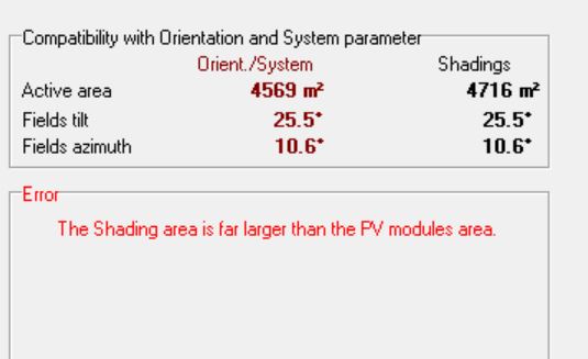
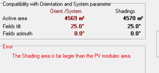
In fact, first it was larger but then I deleted some modules to (maybe) avoid the error.
I changed the hidden parameters and tried both, the "normal" amount of modules and less modules. Nothing changed.
-
I am not able to simulate anymore, there is always this error...Any suggestions?
-
Okay, I have sent you a mail...
-
And just ignore everything? Why is this happening?
-
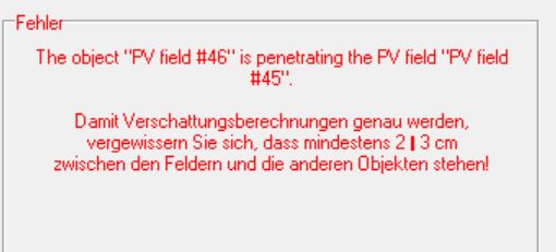
Hello, I have problems with the Import. I tried with a small plant and there have been no problems but with a larger plant, there are a lot...
What I did:
1) Imported a DAE-3D-file from AutoCAD -> the tables are "objects"
2) Transformed to PV faces
3) Deleted the objects -> just PV-fields
What happens: A lot of warnings like "the object "PV-field #46" is penetrating the PV-field "PV-field#45"." In fact, the distance between the tables is 10 cm (so >2-3 cm)
If i delete this table, it happens somewhere else.
Any hints?


Convert Object to table zone
in Suggestions
Posted
Hello,
since it is possible to import Objects and it is also possible to create tables within a "table zone" - it would be very helpful to be able to convert an imported object to a table zone.
Any thoughts about this?
Regards,
Lockyy