Lockyy
-
Posts
14 -
Joined
-
Last visited
-
Hello, since it is possible to import Objects and it is also possible to create tables within a "table zone" - it would be very helpful to be able to convert an imported object to a table zone. Any thoughts about this? Regards, Lockyy
-
Anybody from the PVsyst can answer this? I tried the tool Electrical behaviour of PV arrays for th version 1) and it showed me for the shadow of 20 submodule (1 diod), that the U_Mpp is already close to the U_MPP-range. If 40 submodules are shaded (2 diods), the U_Mpp is already out of the U_Mpp_range. If I have version 3), the maximum shaded submodules would be 15, so everything within the U_Mpp_range. So I think it is definitly the better version! Can somebody from PVsyst answer me?
-
For 3: When the last module is shaded, the MPP-Tracker will finde same current at a different voltage and skip the modules. So IF the rest modules have enough voltage to bring it to the mpp-range, I lose 20 modules -> 1/4 of modules, the rest is normal. For 1: Same situation, I lose 1 string of 20 modules completly -> 1/4 of modules, the rest is normal. It gets more complicated if I even consider the bypass-diods and only shading at the very bottom. For 3: The string l lose 1/3 of 20 Modules (MPPT finds the MPP and skipps the last diods) For 1: For the last string, IF 2/3 of the voltage is in the MPP-range, MPPT finds the MPP and skipps the last diods. -> I lose 1/3 of 20 modules BUT: If 2/3 of the modules are shaded: For 3: the string have the voltage of 15 full modules and 5 modules with only 1/3 of voltage, it is still possible to find the MPP and skip 2 bypass-diods each. For 1: for the last string we only have 1/3 of voltage for 20 modules, so it will probably be outside the MPP-range -> I lose the string completely. So in the end I have the MPPT and bypass-diods for finding the voltage with the "full" current. Or do I miss something? In my opinion therefor it is better put only 5 shaded modules in one string each, so worst case you have 15 non-shaded modules with enough voltage. But I do not have english literature for this, just german one: https://photovoltaikbuero.de/pv-know-how-blog/teilverschattung-solargeneratoren-teil-33/
-
Hello, I have a question. If I have rows of tables 4x20 More possibilities for the stringing: 1)Each row is one string: _________ _________ _________ _________ 2)Every two rows are one string: _________ _________ _________| _________| _________ _________ _________| _________| 3) Every four rows are one string What are the number of strings in width and in height: 1) width: 1 hight: 4 2) width: 2 hight: 2 3) width: 4 hight: 1 ??? The simulation shows that 3) ist much worse than 1). But in reality in 3) for each string, only some module will be shadowed in the morning. But as I understood PVsyst, this is not how it works? If the lower modules are shadowed in 3), the whole string is influenced!? Can somebody enlight me?
-
Yes I know. But every time I change the system (less modules, more modules), the mOhm stays fixed and the percentage changes to 1.13% or 0.88%,...I want the percentages to stay fixed 1%.
-
Any ideas anybody?
-
Hello, I am trying to calculate a project and want to compare different inverters and panels. But every time I change the system, the ohmic losess (percent) change. At this point I don't want to vcalculate cables or anything. Is it possible to keep the losses fixed to values like 1% or 1.5% and NOT xy mOhm? If not, is there a chance to make it possible in a future version of PVsyst? Thanks in advance! Lockyy
-
Hey, I have a roof top with a tilt of 6°towards east and now I want to place modules with 15° south on it. Usually I import the modules via Autocad and then change the tilt but it always changes the angle of the former 6°. I even tried to import a module with the correct angles but when I use "transform to PV faces", one of the two angles gets lost. Please find attached a screenshot (sorry for my bad drawing skills...) Any suggestions?

-
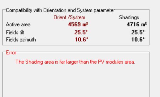
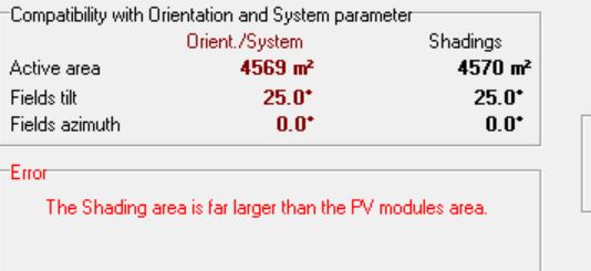
Shading area is far larger than the PV module area
Lockyy replied to Lockyy's topic in Problems / Bugs
I made a complete new project with the same data and now it worked...I even used the same shading. Strange! -
Shading area is far larger than the PV module area
Lockyy replied to Lockyy's topic in Problems / Bugs
In fact, first it was larger but then I deleted some modules to (maybe) avoid the error. I changed the hidden parameters and tried both, the "normal" amount of modules and less modules. Nothing changed.
-
I am not able to simulate anymore, there is always this error...Any suggestions?
-
Okay, I have sent you a mail...
-
And just ignore everything? Why is this happening?
-
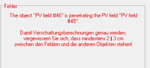
Hello, I have problems with the Import. I tried with a small plant and there have been no problems but with a larger plant, there are a lot... What I did: 1) Imported a DAE-3D-file from AutoCAD -> the tables are "objects" 2) Transformed to PV faces 3) Deleted the objects -> just PV-fields What happens: A lot of warnings like "the object "PV-field #46" is penetrating the PV-field "PV-field#45"." In fact, the distance between the tables is 10 cm (so >2-3 cm) If i delete this table, it happens somewhere else. Any hints?