Javier Perez
-
Posts
8 -
Joined
-
Last visited
-
André, could you give any information about when is it expected to include this improvement?
-
Voltage drop and power losses never could be the same. Really they are different concepts. The formulas for calculation are 2*L*R*I for voltage drop in DC (measured in volts) and 2*L*R*I^2 for power losses in DC (measured in Wats). Since they have different reference values for percentage calculation, by chance it could have the same percentage, but I have not seen such coincidence in any situation. Normally the percentage of power losses are somehow lower than the percentage of voltage drop. Similar situation happens with ac cables between inverter and transformer or between transformer and injection point. As far as I have understand after reading another posts and tutorials of PVsyst, I believe that the software estimates an equivalent resistance to later calculate the power losses taking into account the estimated resistance and actual current. The situation is that you could estimate such resistance wit voltage drop percentage or with the power losses percentage. But I am not sure which value is expecting the software. I hope André could clarify this issue. Best regards,
-
Dear André, I have a doubt regarding the meaning of the parameters expected to define the ohmic losses in PVsyst. The percentage we have to introduce as "loss fraction at STC" is the percentage of the voltage drop or it is the percentage of the power losses of our design. Best regards.
-
Dear André, Just for clarification I could chose only one of the two options, but only one. Is correct? I'm afraid I have another questions regarding the AC ohmic losses. 1.- In scale-utility PV installations, there are normally thee AC voltage levels: LV AC. MV AC and HV AC. So If I want to take into account the ohmic losses until the connection point in the HV level, I should try to add the power losses in MV and HV cabling. 2.- Does PVsyst take into account change in conductor temperature due to the change in current generated? Best regards.
-
Dear all, I would like to know if the simulation is made taking into account the wiring between the inverter and the transformer and also the wiring between transformer and injection point, or it takes into account only the selected wiring. I mean the simulation could be made with both AC wiring losses or only one of the AC wiring losses, one or the other but, no both at the same time. Best regards,
-
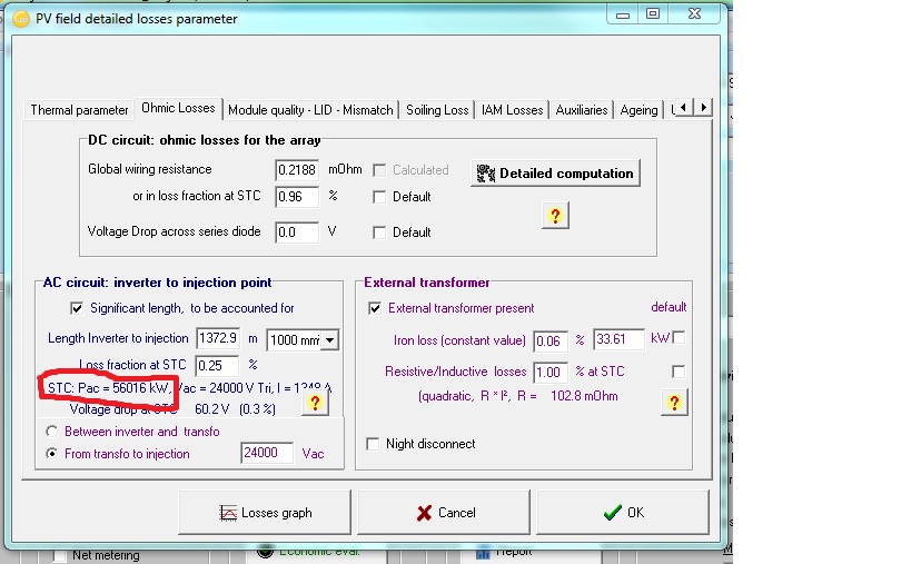
Dear André, In a standard design of a utility scale solar farm we will have one LV/MV transformer every two or three inverters and a global MV/HV power transformer. So in order to simulate all theses transformers I must add the no load losses and the load losses. The doubt is where is defined the value of PNom at STC. I suppose it is the value stated in the AC circuit STC: AC, marked in red in the attached file. Is this hypothesis correct. Best regards,

-
Dear André, I would like to confirm that: * Effective energy at the output of the array is the DC power of the array once all the losses within the panels have been taken into account. * Available energy at the inverter output is the energy in the AC side of the inverter, once all the losses within the inverters have been taken into account. I would like to understand the meaning of the terms "Array virtual energy at MPP", "Array reference energy for PR" and "Array nominal energy (at STC effic.)" Best regards, and thank you very much in advance for your help.
-
I have tried to extract some information, mainly about the energy generated and there are a lot of parameters to be exported, and some of them are not clear, at least for me. Is there a description with the meaning of each of the variables that could be exported? Best regards,