Niken13
-
Posts
4 -
Joined
-
Last visited
-
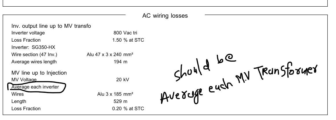
Dear PVsyst Team, I have been reviewing the AC wiring losses in the system, specifically the data provided in the report for the Inverter output line up to the MV transformer and the MV line up to the injection point at 20 kV. Upon reviewing the report, I noticed a potential misunderstanding regarding the interpretation of the "average wire length" in the MV line section. In the report, it mentions: Average wire length for the MV line up to the injection point as 760 meters. However, the way the data is presented could lead to confusion. Initially, it seems that this distance refers to the wiring between the inverters and the MV transformer. But upon further consideration, it seems that the 760 meters should be the distance from the MV transformer to the injection point (where the power is fed into the grid at 20 kV), not per inverter. To clarify: The average wire length should indeed be for the MV line from the transformer to the injection point at 20 kV, and not per individual inverter. The inverter-to-MV transformer wiring and the MV line from the transformer to the injection point are distinct, and it's important to apply the loss fraction of 0.25% to the wiring between the MV transformer and the injection point, where the power is being injected into the grid. Could you please confirm whether this interpretation aligns with how the data is calculated in PVsyst? And, if possible, could you confirm the accuracy of the wiring loss fraction applied to this MV section? Please have a look to the attached screenshot of the PVsyst report. Looking forward to your insights and confirmation. Best regards, NIken

-
and also please let me know is it ok to import 3D scene as a .DAE file in Pvsyst version 8.0.7?
-
Hi I will update directly at support@pvsyst.com. Thank you for consideration.
-
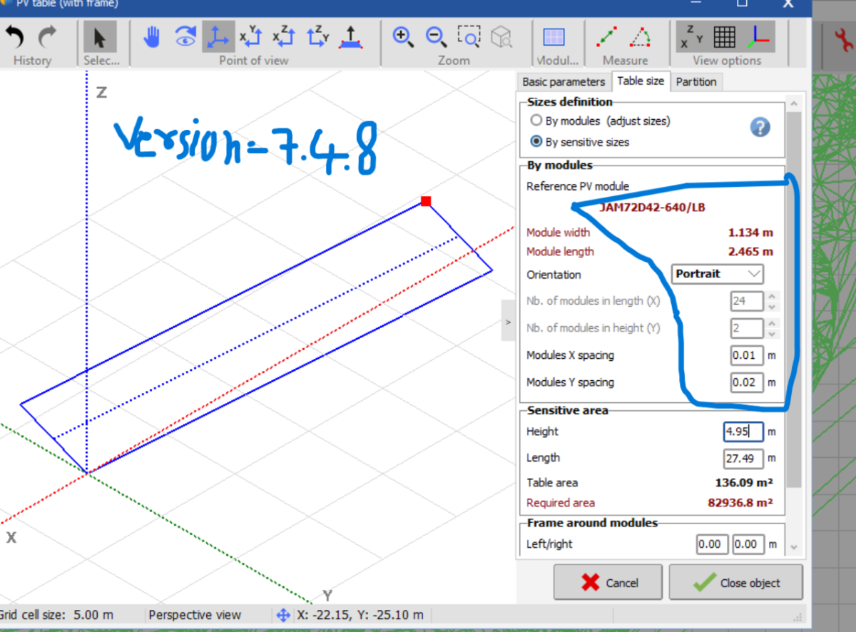
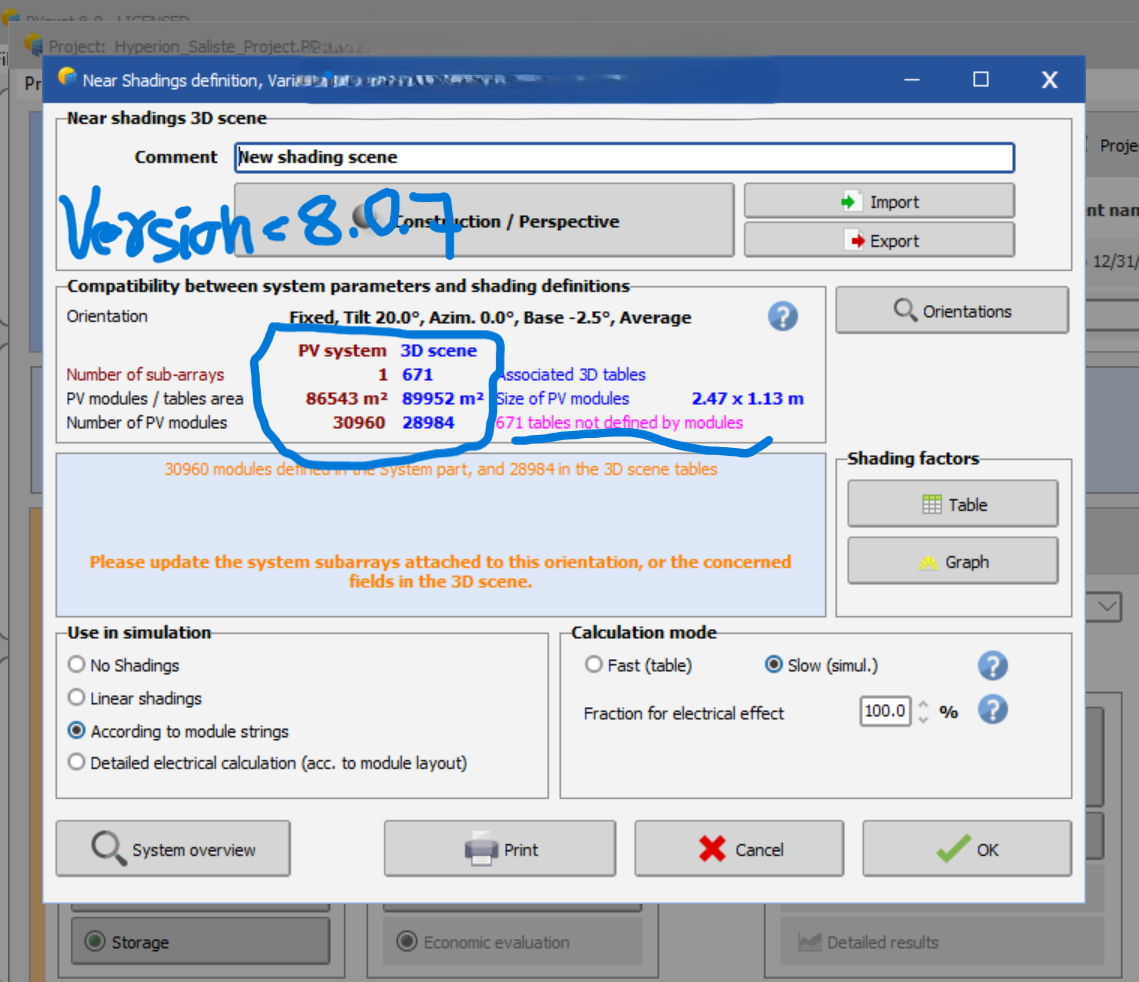
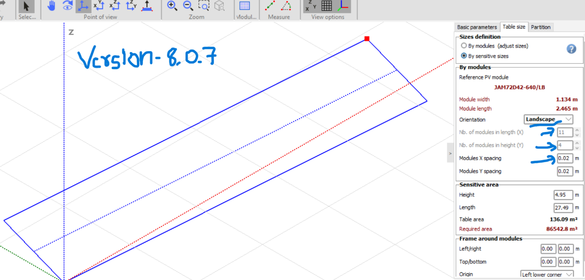
Dear PVSyst Support Team, I am facing an issue in PVSyst versions 8.0.6 and 8.0.7 where certain 3D scene parameters reset after saving and reopening a project. This issue was not present in version 7.4.8. Issue Description while working with PVsyst version 8.0.6 ND 8.0.7: I import the 3D scene using a .DAE file, setting the module orientation to portrait and the X-distance between modules to 0.01. After saving and closing the project, when I reopen it, the orientation changes to landscape, and the X-distance resets to 0.02. As a result, the number of modules in the 3D scene changes, and I am forced to re-import the 3D scene every time I open the project to restore the correct layout. Additionally, after reopening the project, I receive a warning saying "671 tables not defined by modules"—even though all tables were correctly defined with modules when I initially imported the 3D scene. The module count in the 3D scene and in the System definitions matched perfectly before saving. This issue only appears after reopening the project. Please have a look to the attachments. Environment: PVSyst Versions: 8.0.6 and 8.0.7 (issue present) PVSyst Version 7.4.8: Works correctly, no reset of orientation or spacing Import Format: .DAE file Request: Could you please investigate this behavior or advise on a workaround? It seems like the 3D scene parameters are not being retained properly in the newer versions, and this is disrupting the workflow. Thank you for your assistance. Regards, Niken