Luis Zimmermann
-
Posts
10 -
Joined
-
Last visited
Recent Profile Visitors
597 profile views


-
What is the difference in the calculation model (do both use the similar view factor model? ) between the calculation of ReflFrt / ReflBak (close ground reflection) and AlbInc (far ground reflection)? And is the far ground reflection included in the rear side irradiance GlobBak?
-
Can you please explain a bit more detailed the difference between the calculation of beam and diffuse components for the front and for the rear side? And what about the AlbInc (reflected irradiance from the far ground), how is this component calculated for the front and for the rear side?
-
Hello together, is the calculation process of the beam and diffuse component on the rear side of a VBPV system (bifacial model) the same as for the front-side? If not, please explain me the simplification and differences.
-
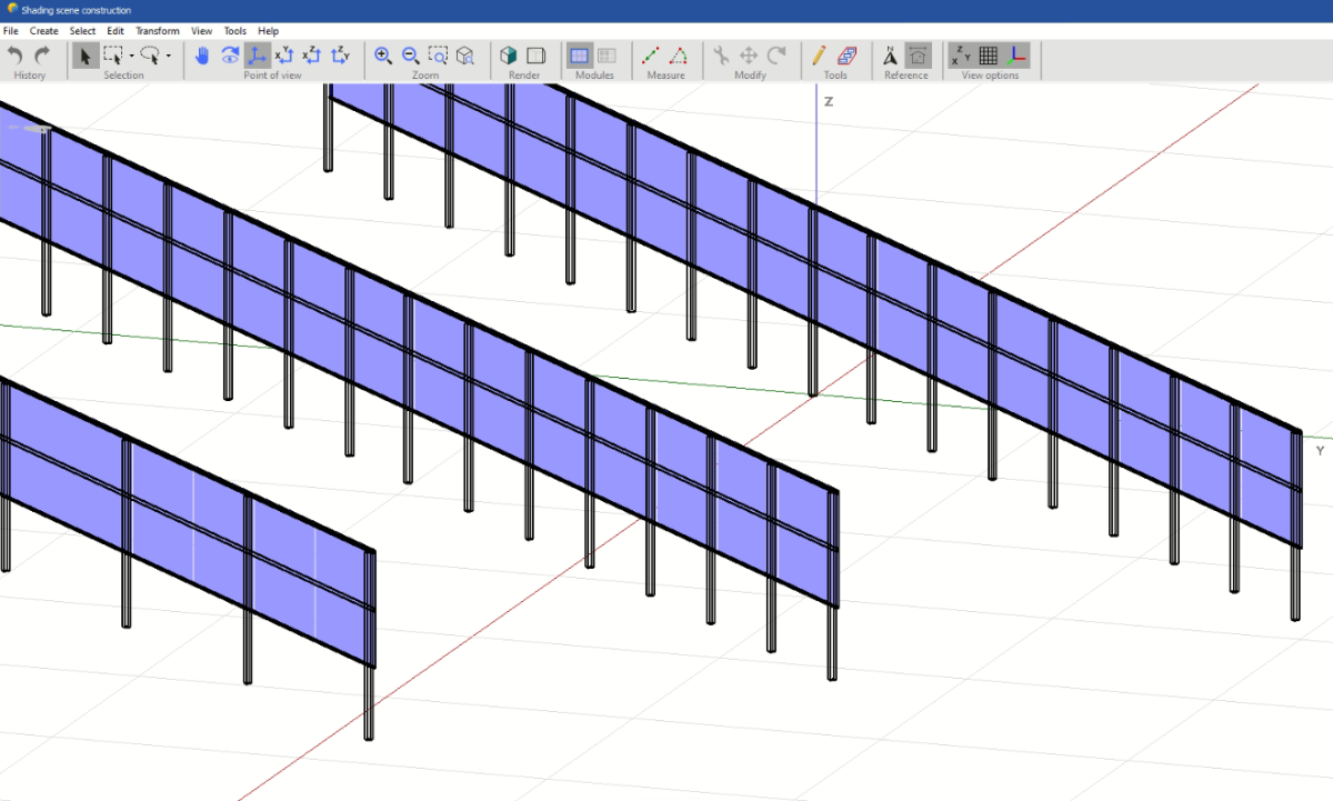
The issue is the the rear shading factor is applied at all hours of the day and to all irradiance contributions (direct beam, diffuse, reflected). I tried to play around with this factor, but it seems not to work. Is there any possibility to simulate the rear side for a vertical system like the front side? In my opinion the differences between front and rear side are only: - Bifaciality factor for rear side - no AR coating on the module glass - Mounting structure shading (can be added in 3D shading scene)
-
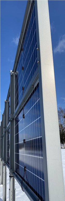
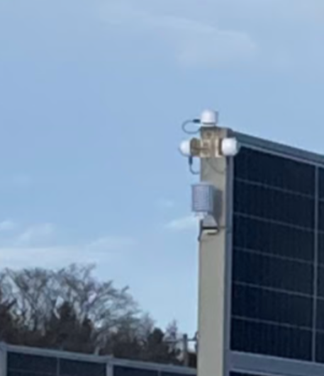
The attached picture shows the rear side of my VBPV system. (the front side isn't shaded by the mounting) To reflect the shading of the mounting system, I tried to add the mounting structures in the 3D shading scene. The limitation is that I have to keep a minimum distance of the 2-3cm from the module to the piles. The simulation result stays the same with and without the mounting structure. Which setting do I have to choose to reflect it within the bifacial model? (if I put the mounting structure on the front side, it influences the result)

-
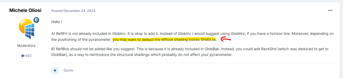
Thanks for all your answers! Could you explain again why you propose to deduct the the diffuse shading losses in your first answer of this discussion? (Screenshot attached)
-
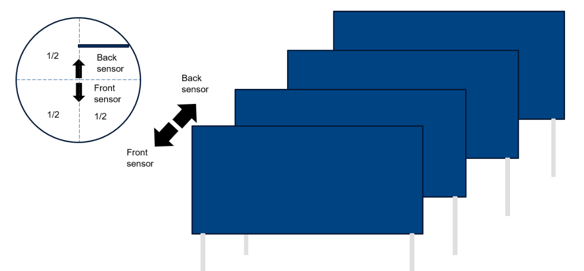
2) Thank you for the recommendation, to add another simulation variant. In my understanding the Pyranometer for the rear side sees other rows, but the albedo contribution should not be removed completely. Attached you can find a drawing which explains my understanding. I would propose to calculate as followed: BeamInc + CircInc + DifSInc + ReflFrt + AlbInc/2 + ( - HrzBLss - HrzCLss - HrzDLss - HrzALss/2) Would you agree with that? 3)The azimuth is -47° for the frontside. That should explain your comment.
-
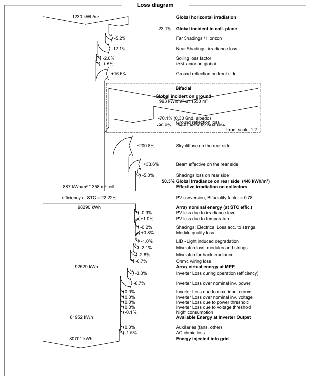
1) Yes, I did enter the albedo in the bifacial model. 2) I attached a picture of the pyranometer placement, it is installed as seen in the first row of the power plant at a height of 3.10m. The power plant has only four rows with a pitch of 8-10m. 3) Attached you can find the loss diagram out of the report. For the front side GlobInc = BeamInc + DiffInc + AlbInc (+ReflFrt), where AlbInc is the reflected irradiance from the far ground. How or where is AlbInc included in the irradiance of the backside, because for vertical solar the calculation for back and front side should be quit similar, compared to modules with a tilt of f.e. 30 degree (there the front and back side irradiance calculation is definitely more different).
-
Thanks for the response! For B) I followed your advice. In result I get now around 50% more irradiance on the rear side from the measured operation data compared to the simulation within the winter months (Jan, Feb). By adding ReflBck I got a deviation of around 10% in the same months. The power plant is located in a snowy region, thats why I use an albedo factor of 0.7 for those two months. Do you have any idea where there could be a mistake?
-
Hello together, I want to analyze the deviation between measured pyranometer data and the simulation output data. The investigated project consists of vertical bifacial PV modules on a agricultural land. On the site there are three pyranometers measuring GHI, front irradiance and back irradiance. To compare the measured irradiance and the PVsyst data I am unsure which simulation variable to use. My current idea: A) Front irradiance = GlobInc + ReflFrt I use GlobInc instead of GlobEff, because the front-pyranometer is not affected the same of the optical losses (shadings, IAM, soiling) like the modules. Question 1: Is that assumption right? Question 2: Is ReflFrt already included into GlobInc? B) Rear irradiance = GlobBak + ReflBck Question 3: Is ReflBck already included into GlobBak? Please answer the three questions and give me general feedback on what to consider for the comparison between measured operating data and simulation output data. Many thanks in advance!