-
Posts
58 -
Joined
-
Last visited
Everything posted by Robin Vincent
-

Large Discrepancy in Total AC Power After Simulation
Robin Vincent replied to Jherche's topic in Simulations
There is a known issue where the total AC power in the report is not accurate with SolarEdge subarrays. This is due to the way the total is computed in the report, based on individual MPPT powers. With SolarEdge and its specific way to attribute (and distribute) strings to inverters, the computation is sometimes incorrect. This issue is on our roadmap, but as it does not impact the simulation results, it has been scheduled for a later version. -
In both versions an issue may happen for systems using the power shifting strategy with transformers losses. The issue happens when most of the PV production is diverted to the battery or most of the grid injection comes from the battery. In these cases the AC losses computation may lead to unrealistic values. This issue will be corrected in the next release. In the meantime, users are strongly advised to use PVsyst 8.0.17 for projects using power shifting.
-
Optimizers won't necessarily increase the system production. Optimizers are especially useful when a part of the string is partially shaded, and has a different Impp (current at max power point) from the rest. Without optimizers, the whole string have to use the current of the worst module, leading to a lower overall production. With optimizers, the shaded and unshaded modules can operate at their own optimum current, the optimizers ensuring the output current to be the same. But when you don't have partial shadings, optimizers cannot improve anything. And since optimizers have their own efficiency, they end up increasing the system losses, leading to a lower PR.
-
For SolarEdge system there is two different advanced parameters limiting the Pnom ratio, one for inverters with less than 25kW nominal power, on for more than 25kW. Since the 50kUS is set to 16.7kW (1/3 of the physical inverter), the <25kW parameter. Please check these parameters in the advanced parameter menu (Settings => edit advanced parameters) You should be able to simulate your system if you change the parameter 404 to something higher than 39%
-
This is a known, but benign, issue where the total AC power is not always well recomputed when you have inverters with MPPTs connected to varying DC power. This is due to the total AC power being the sum of each MPPT equivalent AC power, itself based on the power sharing options. This approach is necessary to be able to deal with fraction of inverters, but may lead to small discrepancies in total. We will solve that in a future PVsyst version.
-
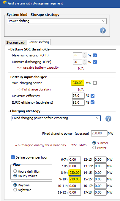
Since PVsyst 8.0.17, you have the possibility to use the "power shifting" strategy in Grid storage. If you do so and select "Fixed charging power before exporting" you can set it to charge as much as possible between 8 and 10. If the charging power is higher than the PV production, nothing will be injected to the grid. The main limitation for the moment is that any value you set will be applied every day for the whole year. Time series import should be available starting from PVsyst 8.1.0
-
Again, if you change any figure for the battery, it WILL impact your simulation. If you change the number of cells or the number of blocks or the number of racks, the battery characteristics will be impacted (voltage for the components in series, capacity for the components in parallel). The only issue I can see is the display of the number of UNITS in the grid storage window, which is not changed as it should when you change the number of blocks in the battery component. Now, if you have this values in your report (10*2 Units) but did not set 10 racks in series and 2 racks in parallel, please contact us at support@pvsyst.com with your project so we can have a better look at what's happening.
-
I think you misunderstood what I meant. You can any number of cells, modules and racks and it will be taken into account during the simulation. Only this specific figure displayed here is false. But that's only for display, so it won't impact your simulation.
-
The "number of elements" displayed might be misleading, as it should represent the total number of cells in your system, but it does not seem to take into account the number of blocks (or modules). This is definitively a bug, but as long as the total voltage and capacity are consistent with your design, the computation will be valid.
-
Hi, From the information you provided, this behavior does not seem normal indeed. The 1st graph looks ok, having 5.8% losses due to the grid limitation with 320kVa installed and 250kVa does not strike me as unusual. The fact is has been lowered to almost nothing in the second case is strange. I tried to reproduce your test case, but the results I obtain are correct. Please contact support@pvsyst.com and share your project so we can have a better look at what's happening.
-
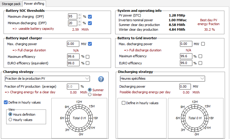
Grid Storage Release note : New strategy of power shifting, from the diurnal PV production to a period offering a better tariff A new grid storage strategy is available : Power shifting. It allows for storing part of the produced energy during the day, then releasing it when the PV production is lower. This option is accessible in Storage => Power Shifting More details in the dedicated help page : https://www.pvsyst.com/help/project-design/grid-connected-system-definition/grid-systems-with-storage/power-shifting-storage.html This update also brings a few minor correction related to how the battery charger and inverter losses are computed. It may impact existing simulation results for all grid storage strategy. These changes should be especially visible in the following conditions : Battery charger / inverter is undersized (e.g : Charger power < PVpower-Grid limitation) Battery Charger / inverter power is largely oversized (e.g : Charger power >> PVpower-Grid limitation) Battery Charger / inverter efficiency is low NB: This new feature is likely to be updated in the future releases, so results are likely to change a little.
-
Compatibility rules between optimizers and inverters are implemented in PVsyst directly based on Huawei's requests. In this case, Huawei requested the maximum connected power to be limited to a certain DC/AC ratio. This is what is displayed in the message box: with only two MPPT input used, the maximum allowed DC/AC ratio is 1. Because you have a total connected STC power of 30.6kW, this configuration is not considered valid for Huawei. Huawei asked us to strictly enforce their rules, so there is no possibility to overstep this one. The only solution is to change your system somehow (configuring more strings, or slightly altering your inverter AC power or modules power so keep the DC/AC ratio below 1). Nb: Mixed orientation are only applied to different strings, not on different modules within a string. Since you can individually assign strings to each MPPT inputs with Huawei, the concept of mixed orientation is redundant and often misleading. In future releases, the mixed orientation option may not be possible anymore with Huawei, and you will have to separate your subarray into two, each with its own orientation.
-
Bonjour, PVsyst ne permet pas la création de chaine de modules avec des orientations différentes, optimiseurs ou non. Si les deux orientations sont suffisamment proches, vous pouvez utiliser l'option d'orientation moyenne dans la scène 3D. La valeur de l'orientation utilisée pour la transposition sera celle de l'orientation moyenne, mais les ombres seront calculées sur la base de l'orienation réellement définie dans la scène 3D.
-
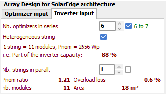
Optimizers Release note : Optimizer efficiency is now applied after module related losses The operating point at the optimizers input was previously computed before some losses that were purely module related. With this correction, all the usual array losses (except for the ohmic losses) are now applied before the optimizer. It may slightly change the input voltage, current and power, leading to a different optimizer efficiency and/or clipping losses. It will also be visible on the loss diagram, with the optimizer related losses now applied just before the ohmic losses. Release note : Optimizer: Power clipping is now better handled. When the optimizer(s) operating point at MPP is outside its nominal current or power, it must be shifted along the input IV curve. Before PVsyst 8.0.15, this shift was simplistic. For an overpower situation, the new power was set to nominal optimizer power, the voltage stayed the same and the current was reduced accordingly. A similar method was used for an overcurrent situation. For small overpower or overcurrent, the operating point shift is small enough that most collateral effect can be neglected. But for larger values, it may lead to unrealistic operating points at module and inverter level. The new algorithm is now similar to what is done with inverters. When clipping occurs, a new module operating point is selected on the IV curve, and the subsequent losses are recomputed. The consequences for most systems should remain small, but it will impact most projects using optimizers. Release note : Optimizers, SolarEdge: it is now possible to define subarrays with heterogeneous strings. When designing a subarray with SolarEdge optimizers, it is possible to have a string of optimizers in which all but one of them are connected to 2 modules. This so-called "heterogeneous string" is now possible to model in PVsyst. In a subarray with SolarEdge optimizers, if there are exactly two modules in series at the optimizer input, a checkbox will appear: When checked, the last optimizer of the string will be set with only one module, while all the other ones will have 2. In this example, one can see that there are 6 optimizers in series, for a total of 11 modules per string. Storage Release note : Grid storage: revision of battery operation calculations The battery control strategy has been reworked, leading to a more accurate implementation of the deratings at low and high SOC. This update may impact projects using a battery that often reaches its min or maximal SOC. Shadings Release note : 3D scene: small width changes in PV table dimensions (<3cm) now modify the total sensitive width/height The PV table dimensions (PV module + inter-module spacing + inactive band) were saved individually in the 3D scene, however small changes in the different components (below 3cm) did not trigger the computation of the total combined width or length. When opening old projects affected by this bug, the total "sensitive" width/length of PV tables will be recomputed. This can have a small impact on the shading computation. Release note : Trackers, diffuse shadings: "central tracker" and "custom tracker" modes now offer the choice of including shading objects in the calculation For trackers, diffuse shadings can be sped up by computing shadings only on a single (representative) tracker. The options "central tracker" and "custom tracker", which implement this choice, can be selected in the 3D scene > Tools > Trackers diffuse shadings definition window. In these two cases, shading masks (i.e., objects that cast shadows on the representative tracker) are selected by PVsyst. Up to version 8.0.14, only neighbouring trackers with the same orientation could act as shading masks. From version 8.0.15, by default, shading objects in the scene are also used as shading masks. A checkbox permits the exclusion of shading objects, effectively reverting to how 8.0.14 functioned. This choice is written in the simulation report. More information on this feature will be available on the help page https://www.pvsyst.com/help/project-design/shadings/calculation-and-model/diffuse-losses-with-tracking-systems.html
-

Turning on Bifacial when using 2 different module types of different size
Robin Vincent replied to Jig's topic in How-to
If you have only two types of modules in your system, you can still create two orientations. One to be used for all subarrays of the 1st type, the other for the 2nd type. These two orientations can have the same parameters, but it will allow you to setup your bifacial system with two module sizes. -

Turning on Bifacial when using 2 different module types of different size
Robin Vincent replied to Jig's topic in How-to
The issue lies in the fact the bifacial model is linked to the subarray orientation, but the modules information are from the subarray. I guess from these messages that you may have two subarrays with different modules sharing the same orientation. One easy workaround would be to define two identical orientations, and set one to each of your subarrays. The main drawback of this solution is that your two subarrays won't cast shadows to each other on their rear sides (since the "unlimited" model used for the rear side is only considering mutual shadings). -
To be able to change the number of rows in the batch, you need use the "unlimited model" or to have a fairly regular 3D scene. You'd also need to make sure your system design is compatible with the modified number of rows. If these points are correct on your side and you are still facing issues, please contact the PVsyst support (support@pvsyst.com) with your project.
-
The SolarEdge SE50KUS uses SolarEdge so-called "synergy technology". It basically makes the inverter behaves as 3 separate inverters. In PVsyst this feature has been modeled by having this inverter set as a 1/3 of the total system. It means that you should always have a multiple of 3 for the total number of SE50KUS inverters if you want to use the whole real system.
-

Finding out the reflection caused by the solar panels
Robin Vincent replied to Adeline's topic in Simulations
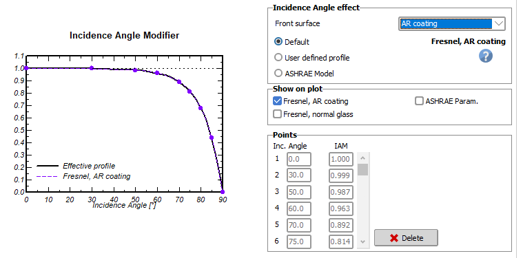
Regarding the direction, as Michele mentioned, the best way would be to find a dedicated glare tool. Alternatively, you could compute the direction yourself based on the sun position and the modules orientation. For the quantitative part, you could use the IAM values of your PVmodule, the incidence angle and the incident irradiance to estimate the reflected energy. -
This post aims to present the main differences a user can encounter when using PVsyst 8.0.12 compared to PVsyst 8.0.11, including PVsystCLI. New functionalities for PVsyst CLI Three new parameters have been added to the run-simulation command: --batch-params-file (-bpf) --batch-rvt-file (-brf) --recompute-shadingfactors-tables (-rst) The two first will allow running a batch of simulations from CLI, thus enabling automatized parametric studies. An example use case has been added to the page https://www.pvsyst.com/help-cli/use-cases/simulation.html The third option allows choosing whether shading factor tables should be recomputed at the beginning of the simulation. More information on the commands and their usage can be found at https://www.pvsyst.com/help-cli/reference/index.html Correction impacting the modeling of optimizers Release note: Optimizers: Minor update of the optimizers MPP choice under partial shadings with module layout shading model When using the “module layout” shadings model, the MPP tracking algorithm now works better during partial shading conditions. In previous versions, it used to select an MPP at low voltage output, sometimes leading to inverter minimum voltage related losses. This correction may lead to a slight production increase, mostly from a reduction of inverter voltage threshold losses. Other minor corrections in the context of the modeling of optimizers concern Huawei optimizers : Correction of the efficiency computation, leading to a slight increase of the optimizer efficiency losses. With long strings (i.e., when the string voltage at STC is higher than the inverter MPP input maximum voltage), the individual optimizers' operating point selection now takes into account the minimum inverter input voltage. Under low-light conditions, this may improve the inverter efficiency by selecting a higher voltage operating point. Updated Bifacial PR The bifacial PR is now available in the report and in the monthly result tables. Its abbreviation is “PRBifi”. Note that the definition was also updated to now take into account the bifaciality factor. For more information, please check https://www.pvsyst.com/help/project-design/results/performance-ratio-pr.html
-

Iso-Shading Diagram when no shading object is present
Robin Vincent replied to PVsystUser's topic in Shadings and tracking
I guess, based on your scene the trees are not the major contributors to the shadings. It could be that all your rows don't have the same height, which is not taken into account in the backtracking algorithm. It could also be a bug. At the very least you should try it with the latest PVsyst version to see if you get your expected outcome or is the shadings are still looking similar. But again for this kind of questions you should contact PVsyst support instead of using the forum. There is only so much we can say based on a few screenshots. -

Iso-Shading Diagram when no shading object is present
Robin Vincent replied to PVsystUser's topic in Shadings and tracking
Dear User, It is kind of hard to analyse why your scenes yield different shading tables based on screenshots. For questions specific to your projects, please contact PVsyst support directly with your project : support@pvsyst.com. Regarding your first question, the iso-shadings diagrams are not identical (clearly visible on the "40%" line at the bottom which is higher on the left graph). That seems consistent with the shadings losses being higher on the left too. I won't be able to answer the second question without the actual project. Have you tried it with PVsyst 8? For the 3rd question, if the backtracking is enabled it might be possible you don't have mutual shadings at all. -
There are two main differences between ReflFrt and AlbInc. AlbInc uses the albedo value defined in the project setting, while ReflFrt uses the albedo defined in the bifacial model. The far albedo is only seen by the 1st row, while ReflFrt is computed for all tables. The computation itself is also slightly different (integral of visible sky portion vs integral of the reflection on several ground points) but this should have a extremely small impact on the final results.
-
The unavailability period represents the time during which your system won't produce any energy. So yes, if your inverters are in average unavailable 2.5% of the time, you can set it as the unavailability time fraction for your system.
-

Huawei rules problem for SUN5000-150KTL-MG0 with optimizer 1300s
Robin Vincent replied to Timothy's topic in Simulations
For Huawei optimizers, we are strictly applying the rules requested by Huawei. In this case, they requested between 9 and 12 strings per inverter for the sun5000 series. Please contact Huawei directly if you think a modification to this rule is necessary.

