Andrés Fernández
-
Posts
12 -
Joined
-
Last visited
-
Hello, thank you for your response. Is it possible to add these variables manually? If precise measurements of GPOA, DHI, DNI, and GHI are available, is there a way to use those measurements directly in the calculations in order to avoid the uncertainty associated with the models? Thank you.
-
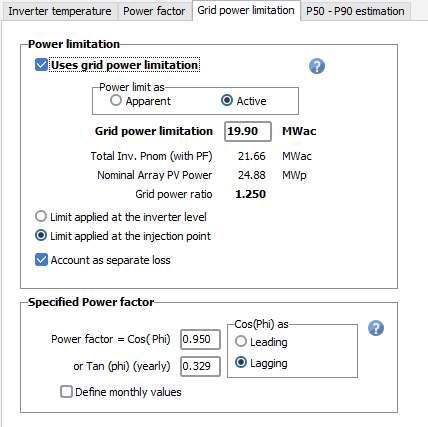
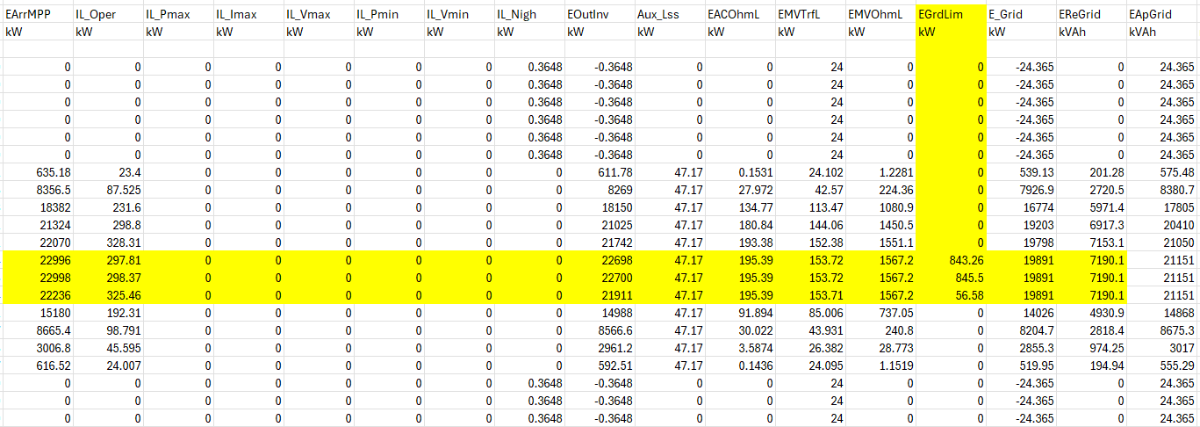
Hello, I have noticed a behavior when simulating a PV plant with an active power injection limit at POI. In the output CSV file, the power seems to start being limited slightly before reaching the configured threshold in the simulation settings. I am attaching a screenshot of both the CSV output and the configuration parameters for reference. Could you please clarify why this limitation is applied earlier than the set value? Is this an intended behavior in the model or is there a specific setting that I should adjust? Thank you for your support. Best regards,

-
PVSyst unexpectedly closes during long batch runs
Andrés Fernández posted a topic in Problems / Bugs
Hi When I run large batches (many simulations) PVSyst runs for a few hours then suddenly closes without an error dialog. I’ve tried smaller batches without problems and monitoring Task Manager but can’t find a clear cause (like memory spikes). Any suggestions on logs to collect, known bugs, or settings to stabilize long batch runs? PVSyst Version: 8.0.14. OS: Windows 11 (full updated). RAM: 16 GB. Thanks in advance -
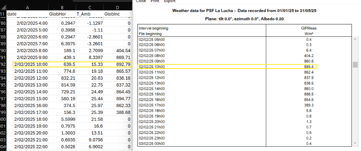
Hi everyone, I've noticed something curious while working with a custom .MET file that includes field-measured irradiance in the plane of array (GIPMeas). After running a simulation and generating the 8760 output file, I've seen that the GlobInc values sometimes differ from the GIPMeas values input. I understand that GlobInc represents the global irradiance on the plane of the array, but I was expecting it to match the GIPMeas data directly, since that's what I used in the .MET file. I’m attaching a screenshot showing a comparison between GIPMeas and GlobInc for reference. Does anyone know why these differences occur? Is there some internal processing or adjustment done during simulation that could explain this? Thanks in advance!
-
Inverter output power by .OND file
Andrés Fernández replied to Andrés Fernández's topic in PV Components
Thank you for your response. Does the linear extrapolation you mention use all points or the last two points of the table? Regards, -
Hi everyone, I’ve run into something odd in PVsyst and I’m hoping someone can help clarify what’s going on under the hood. The situation: I’m using an inverter “.OND” file supplied by the manufacturer. In both the Main Parameters and Output Parameters tabs, the inverter’s Maximum AC Power is listed as 1265 kW (at low temperature, so no derating). However, when I look at the DC-to-AC performance curves (DC input power vs. AC output power), the data only go up to 1100 kW—which is the nominal power rating. My questions are: Which number does PVsyst actually use when simulating maximum AC output? Does it honor the 1265 kW value from the parameter tabs, or is it capped at 1100 kW based on the performance curve data? If PVsyst does cap the AC output at 1100 kW, is there a way to override this (e.g. by editing the curve or adjusting settings) so the full 1265 kW is available under ideal conditions? I appreciate any insights or experience you can share—thanks in advance!
-
Hi Muhammed, Thank you very much for your help, I will keep it in mind. Regards,
-
Hi everyone, I'm encountering an issue when trying to generate a simulation report in PVSyst. Occasionally, the software crashes and shows the following error in the log: "Access violation at address 00007FFC2AF3D35C in module 'atio6axx.dll'. Read of address 0000000000000254." From what I’ve found, this seems to be related to the graphics card driver. I'm currently using a Ryzen 7 PRO 8840U processor with integrated Radeon 780M Graphics, and all my drivers and Windows updates are up to date. Has anyone experienced this issue before? Any suggestions on how to fix or work around this problem? Thanks in advance!
-
Got it, I understand this would be done in the near shadings scene. My question was more about whether the plane-of-array irradiance was correctly estimated, considering that both the tilt and the base slope vary. Would the standard practice in this case be to define multiple orientations? That is, grouping different arrays based on their real tilt and real azimuth? Thanks for the support.
-
Hello everyone, I'm working on a PVSyst project where the terrain is undulating, which makes it challenging to define the tilt of the modules properly (for Orientation and near shading scene). I've attached an example image to illustrate the case better. Any advice or references would be greatly appreciated. https://waareeimages.s3.ap-south-1.amazonaws.com/energy_of_the_sun_and_convert_it_into_electricity_5a25f22d3d.jpg Thanks in advance!
-
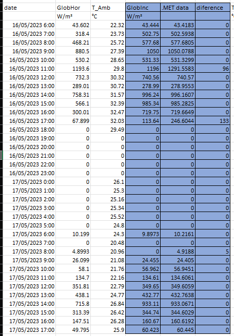
Hello, I am currently working on a project involving GTI irradiance measurements in the field. However, I have observed discrepancies between the GTI values used in the simulation (GlobInc) and those loaded in the MET file on certain days. It is important to note that the system utilizes a single-axis solar tracker. These discrepancies typically occur, in the majority of cases, around 17:00 hours (please refer to the attached image). I would greatly appreciate any opinions or suggestions. Best regards.