Mike
-
Posts
3 -
Joined
-
Last visited
-
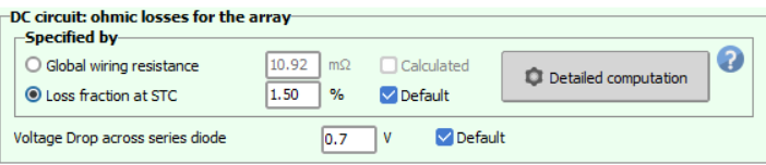
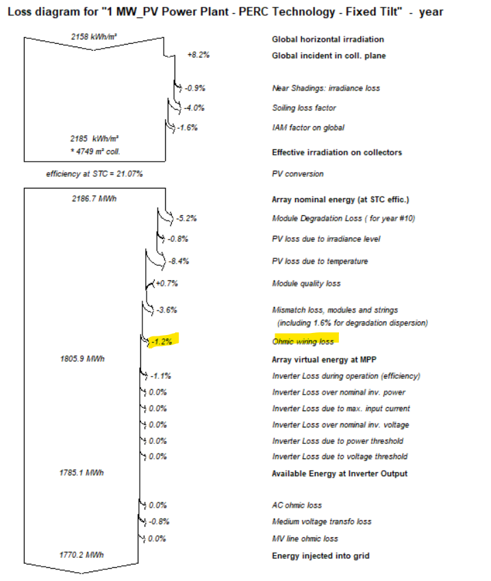
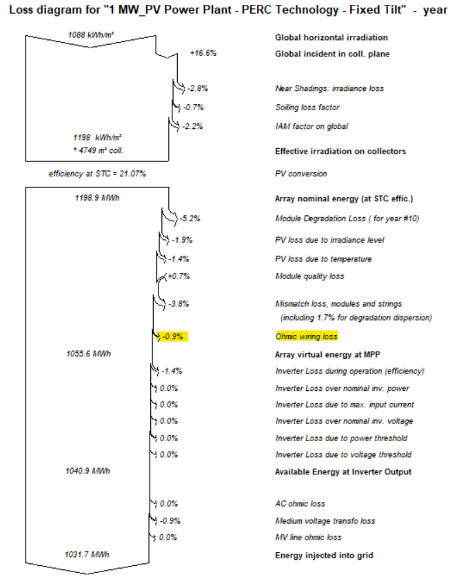
I have adjusted the DC ohmic losses as 1.5% as shown below for a typical PV power plant simulation in 2 different locations (Abu Dhabi & Berlin). However, the loss diagrams for both simulations shows 2 different values as below. Please clarify why the dc ohmic losses% in the loss diagram are different despite assuming the same losses (1.5%) considering identical setup. and provide details of the DC ohmic losses calculations method that leads to the percentages shown in the loss diagram.

-
I have an upper roof and lower roof (tilt angle is zero) - (Flat roofs). So, I believe single Sub-array with "mixed orientation 1 and 2" for each roof would be suitable. Also, I am planning to have either (one inverter per each orientation, so total no. of inverters would be four (two for the upper roof and two for the lower roof)), or (one inverter for each roof with 2 MPPT). What do you think for the above design strategy?
-
I have a roof of 1000m2, and i propose an east west technique for the PV system design. Please review below steps and provide your feedback if the input data of such simulation is correct or not? I presume to simulate such system in PVsyst. the following steps I have considered. I have introduced 2 orientations a)1st to east and with area (500m2) I have chosen the module power and quantities based on the efficient usage of the available area (maximum percentage used of the available 500m2) I have chosen the inverter power rating 20% less than total modules power rating. b)2nd to west and with the same area (500m2) with single inverter I have chosen the module power and quantities based on the efficient usage of the available area (maximum percentage used of the available 500m2) I have chosen the inverter power rating 20% less than total modules power rating.