All Activity
- Past hour
-

Iso-Shading Diagram when no shading object is present
Linda Thoren replied to PVsystUser's topic in Shadings and tracking
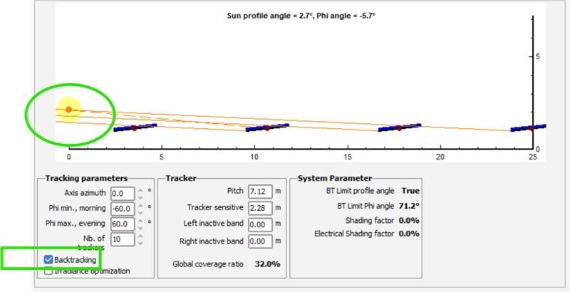
The backtracking is a strategy to avoid mutual shadings. Thus, in the morning and evening when the sun is low, as in your example, the trackers will avoid mutual shadings by tracking "backwards" . If you do not want to have this behavior, deselect the backtracking option. -
distance from ground - zone in PVsyst shading scene
Linda Thoren replied to PVsystUser's topic in How-to
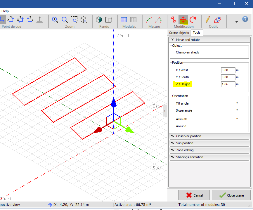
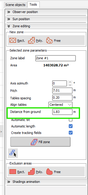
Please update to the newest version If you must stay at version 7, you can mark all the tables and move the selection using the arrow, or define the height in the tools section:
-
Indeed, the loss fraction is set for STC (standard test conditions) and the simulation will be done in real conditions that will vary between sites.
- Today
-
hello my project is bigger one and it has 12 roof of many azimuth and i need a single pvsysts file for it how i can do that i see that using several azimuth max we can put is 8 azimuth thanks in advance for your reply
-
 Morget joined the community
 -
 Madj joined the community
 - Yesterday
-

Iso-Shading Diagram when no shading object is present
PVsystUser replied to PVsystUser's topic in Shadings and tracking
Does PVsyst have any stow- strategy in the simulation when backtracking is on. The reason I am asking is because in "orientation" tab when backtracking is on, the modules will go to stow at sunrise and sunset (when moving the sun in the screen shot below to the extreme ends)
-
distance from ground - zone in PVsyst shading scene
PVsystUser replied to PVsystUser's topic in How-to
My PVsyst version is 7.2.16. -
Ohmic loss is proportional to power. Abu Dhabi has much higher irradiance compared to Berlin. Also, not sure if it is intentional, but you're simulating the 10th year of operation. If unintended, be sure to set it to year 1 on the degradation tab. Ohmic losses - PVsyst documentation
-
distance from ground - zone in PVsyst shading scene
Linda Thoren replied to PVsystUser's topic in How-to
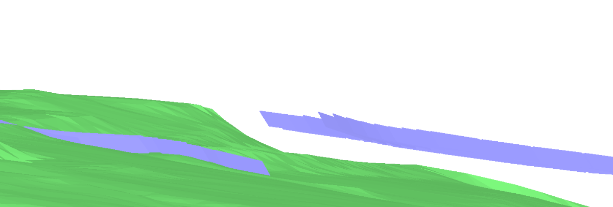
Hello, I did a similar test in version 8.0.18 and is seems to work as it should on my side. The zone to the left is places 0.5m above the ground the the zone to the right 5m above the ground. If the issue persist, please describe further how to reproduce it. Kind regards,
-
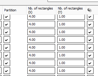
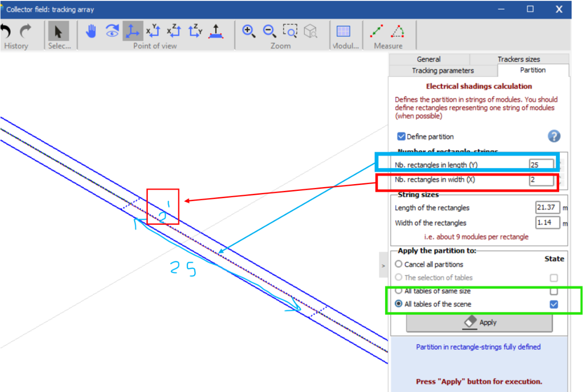
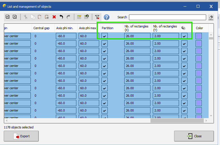
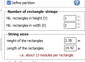
Hello, The two locations to define the partitions are equivalent. If you change one, the other will update. The example below is from the DEMO tracking system Annecy with strings of 20 modules in 2P The partition model is intended to represent the stringing configuration. Therefore, if a table contains one string (e.g., 26 modules), you should define a single rectangle in length (Y-direction), since all modules are electrically connected as one string. If a table contains multiple strings, a separate rectangle should be defined for each string. For example, if a table has 52 modules—corresponding to two strings—you should define two rectangles in length.
-
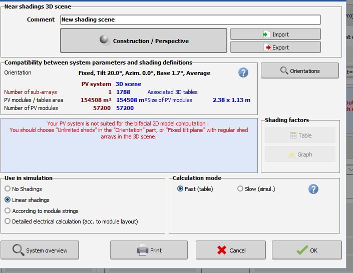
Yes the number of sheds will have an impact of the performance, considering that the first and the last rows are not accounted for in the same way, since they will not experience the same shading patterns as the tables in the middle of the system. When there are many rows, this difference may be neglected. You can read more about the impact in the following help page: https://www.pvsyst.com/help/project-design/bifacial-systems/bifacial-systems-nbofsheds.html?h=number
-
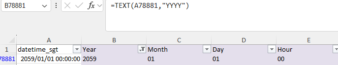
I meant you have to change the date itself from 2059 to 2049 in your csv data before importing. The other files should not be changed. File name should not matter. If you struggle to do it, please send a request at support@pvsyst.com with your input csv data attached
-
 mariem joined the community
 -
Is no of sheds affected the performance, what means by no of sheds, plz elaborate
-
 AHSAN ALI joined the community
 -
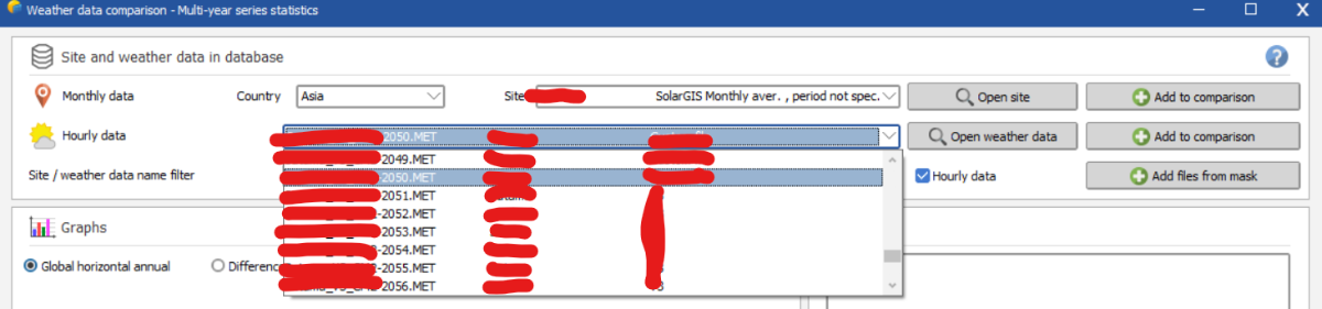
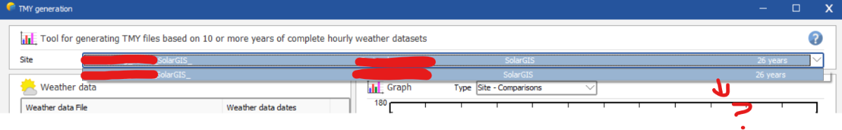
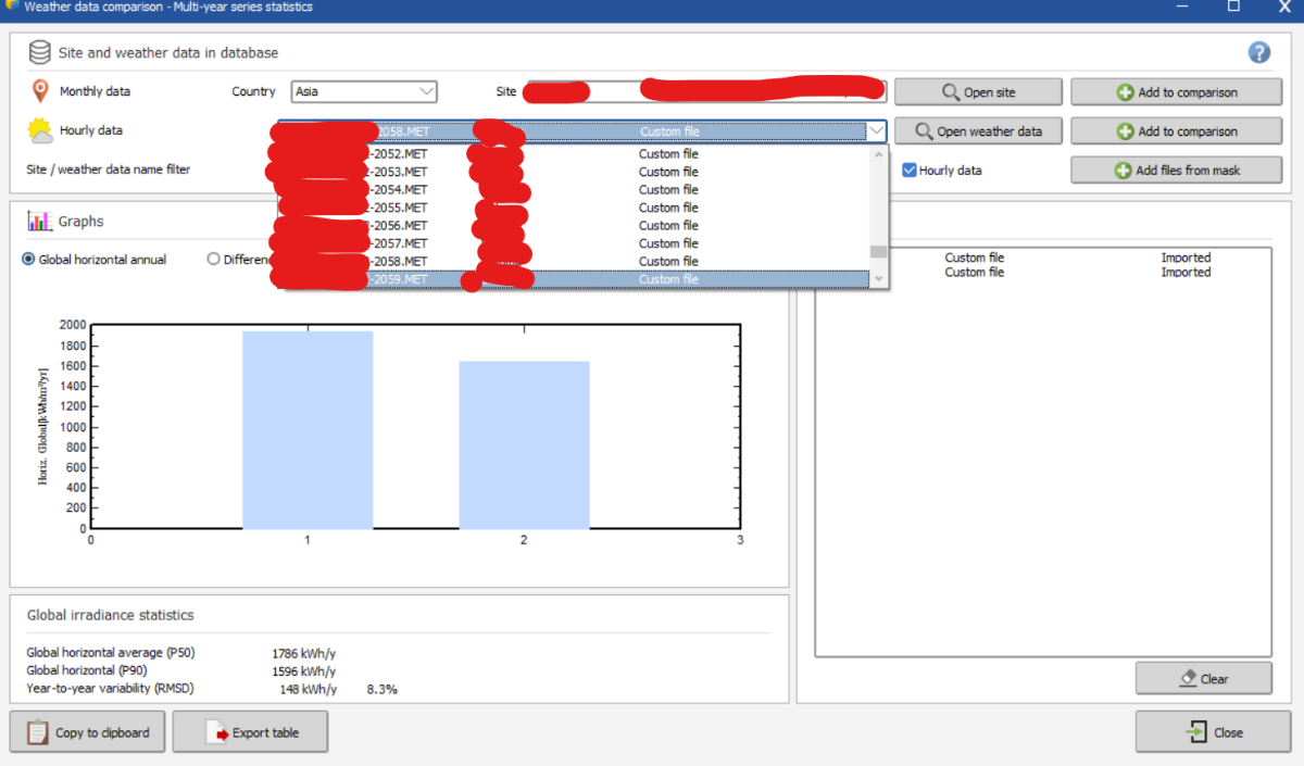
I have changed the labels for the .MET files to 2049-2058 but all of a sudden, I am not seeing any files appearing in the TMY generation tab. Is this another bug in the system?
- Last week
-
 Kalex6307 joined the community
 -
 Arda Fındık joined the community
 -
why not partition like this :
-
We have two location to define partitioning: List and management of objects zoning > filed properties > partition What is the difference between these two and which one should we use? When the string length is 26 in 1P, is the screen shot below, a correct way of partitioning in zoning? if yes, why we use 2 for nb. of rectangles in width and not the string length (number of modules in series)? A visual guide can help a lot. The partitioning in confusing. even in the link below , they don't say where should we put string size? It just says how to define number of modules in height, but how about width? https://www.pvsyst.com/help/project-design/shadings/electrical-shadings-module-strings/partition-in-strings-of-modules.html#summary-for-common-cases
-
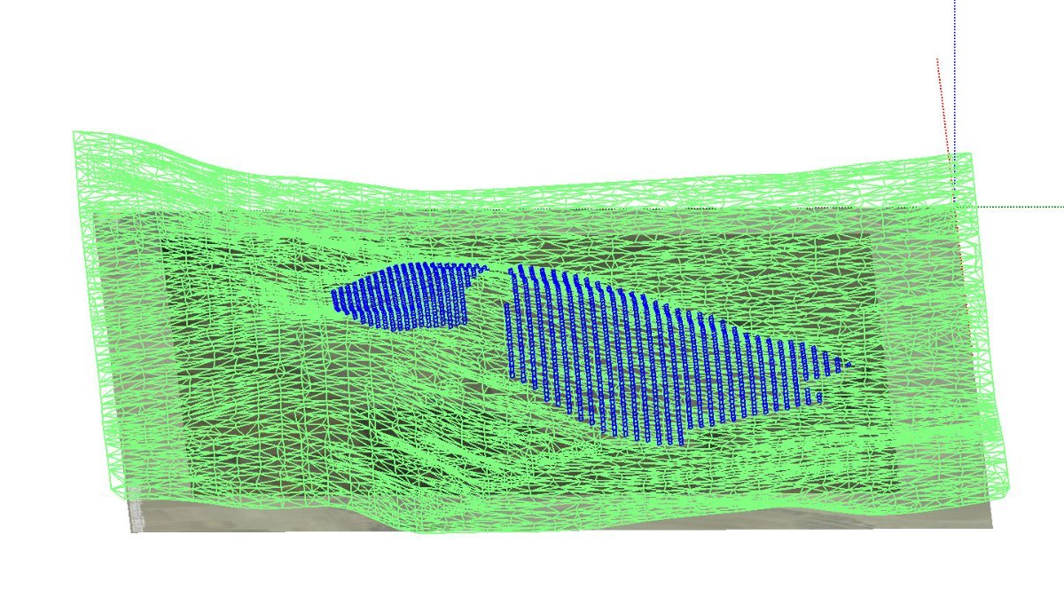
I changed this number to different values ( 0.5, 2m, 30m) and it seems it is not reflected anywhere. at least when having multiple zones with different distance from ground , they all look to at the same heigh :
-
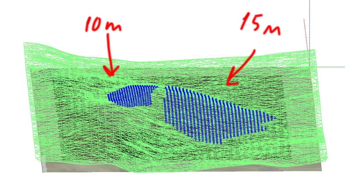
Hello, In version 8 you can create multiple field types in the orientations window and assign different bifacial parameters to different sub-systems. Thus, even if the tilt and azimuth are identical, create 2 orientations and assign each orientation to a sub-array in the system window, corresponding to the two sub-systems with different pitch in the 3D scene. You find a similar example in the DEMO tracking system Annecy, variant VC5: 2 fields of Trackers with different pitch Kind regards
-
Dear Nikoloz, In PVsyst Stand-alone, there’s no inverter component by design: the load (“User’s needs”) is defined as an energy demand (kWh), independent of whether the end-use is DC or AC. If you do have AC loads through a battery inverter, PVsyst’s recommended approach is to model it as an efficiency penalty. They also state the rationale: stand-alone (battery) inverters are fundamentally different from grid-tied PV inverters, so they’re not handled via the usual inverter database and are planned for a future implementation. Regards,
-
 NEILPD joined the community
 -
thanx alot but there is still one question. where to add an inverter >???? unversal controller is not inverter. there is n otion to choose ?..
-
Hello there. I have serious problems with bifacial computation when I have different pitches in one procets ... is this bug or I am making something wrong ?????? I have project where part of panes are located on slope which needs to have 10 m pich and other part which needs to have 15m pitch... the question is how to make it as 1 project ???? or how to seperate it to get 1 simulation figures. Pvsyst gets it as 1 orientation . PS " unlimited sheds " is not a solution. it does not work in this situation
-
 Meklit joined the community
 -
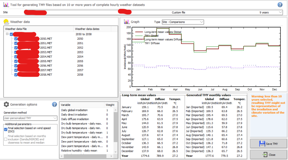
Unfortunately, this is a known bug and I'll ping the developer team about it. In the meantime you should change the year from 2059 to 2049 when generating your .MET file for that year. It won't change anything when generating the TMY from your 10 files that they are labeled 2049-2058 instead of 2050-2059
-
 SONA joined the community
 -

PVsyst v6: Inconsistent Date Format in Hourly Output .CSV File
aspf replied to kjs55's topic in Problems / Bugs
Sorry for the late reply. I ended up using TEXT function.
-
Hi, i have created 10 years worth of MET files for TMY generation from 2050-2059 but when i go to TMY generation tab, it only shows MET files up to 2058. This is a bug? thank you.
-
How can I import a quarter-hourly meteo file into PVsyst?
Linda Thoren replied to Nihal Meena's topic in How-to
Hi, Indeed the custom import process can be a bit tricky. In the upcoming release of version 8.1, we will introduce a new assistant to help guide users more easily through the construction of the .MEF file. When importing sub-hourly data, please ensure that the time step is correctly set to 1 minute rather than the default 60 minutes. The warning message you received indicates that the imported irradiance values are very low compared to the site’s clear-sky model. Is the site correctly defined? If you are importing measured data, it may also be worth checking whether the solarimeter requires calibration or whether the units have been properly specified. Feel free to send us your site and CSV file at support@pvsyst.com so we can take a closer look. Kind regards, -

What does the white part of the Iso Shading Diagram representing?
Muhammed Sarikaya replied to PVsystUser's topic in How-to
Dear, The multiple curves visible comes directly from the shading factor table. See the help related: https://www.pvsyst.com/help/project-design/shadings/calculation-and-model/iso-shading-diagram.html This table is computed on a fixed grid (20° azimuth / 10° height),when fast calculation is choosed, see the help: https://www.pvsyst.com/help/glossary/shadings/shading-factor-table.html?h=table+fa And PVsyst always displays the isolines resulting from this calculation. However, the solar path never enters this region of the diagram that your show in green rectangle. Therefore, even though the iso-shading curves appear there, they do not correspond to any real shading situation. They are simply the graphical projection of the table-factor values in an area of the sun-position diagram that is never reached by the actual sun path. Only where the iso-shading lines intersect the solar trajectories can real beam shading occur. Regards,